Shock Gold Valve Installation Onto the Shaft
|
|||||||
|
|
Tools
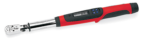
- Torque wrench (SnapOn Digital Torque Wrench shown) - Metric calipers and micrometer
- TMVJ 065 Vise Jaws mounted on a Vise - suggested - TSSB Series Bullet Tool - for Seal Head installation Supplies
Contact Cleaner - or other good, clean solvent
Loctite - Hi-Strength (included in the Gold Valve Kit)
USSG 01 - Ultra Slick Seal Grease
|
||||||
|
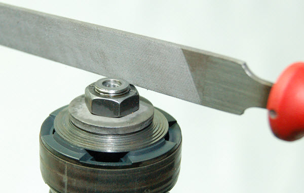
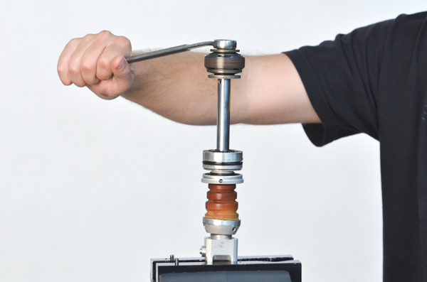
SD1 - Remove the shock shaft nut. On Showa and KYB shocks the nut is peened on. This peening must be removed first.
KYB shocks - On almost all KYBs the peening can be ground or filed off flat. (Except for 1989 YZ125 & 250,1989-91 CR125, and 91 CR250 & 500. See your DVS Sheet.)
WP, Sachs, and Ohlins are not peened and can be removed with a wrench.
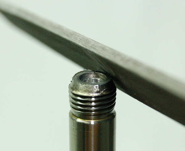
SHOWA NUT REMOVAL
On Showa shocks, the peening also retains the rebound adjuster hardware inside the shaft. The peening should only be removed on the OD where it retains the nut. The peening on the ID must be left intact where it holds in the rebound mechanism.
Remove the peening with a file (you can use a bench grinder too if you're careful.) Remove material only on the outer diameter just enough to remove the nut.
|
||||||
|
|
SD2 - Remove the shock shaft nut and the valving stack.
|
||||||
|
|
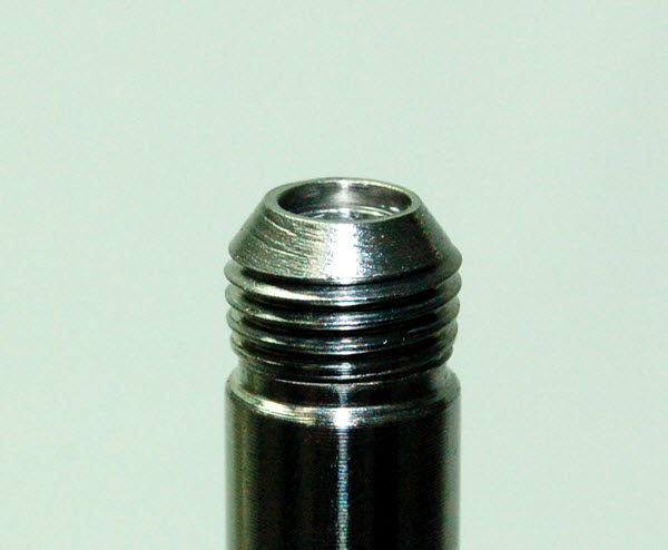
SD3- For peened-on nuts, chamfer the end of the thread with a file or a grinder just enough to clean up the sharp edge. Deburr with a wire wheel.
|
||||||
|
|
SD4- To remove filings, blow air through one of the side feed holes with a rubber tipped blow gun while covering up the other side. Use contact cleaner and repeat.
|
||||||
|
|
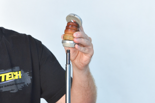
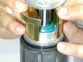
SD5- Remove the seal head, body cap, bottom-out bumper and retaining cup. Some models have slightly different hardware.
Inspect the Bottom-out Bumper for tears or damage. Bumpers are wear items. They break down over time and should be replaced when any signs of deterioration exist.
Bumpers are available at Race Tech.
|
||||||
|
|
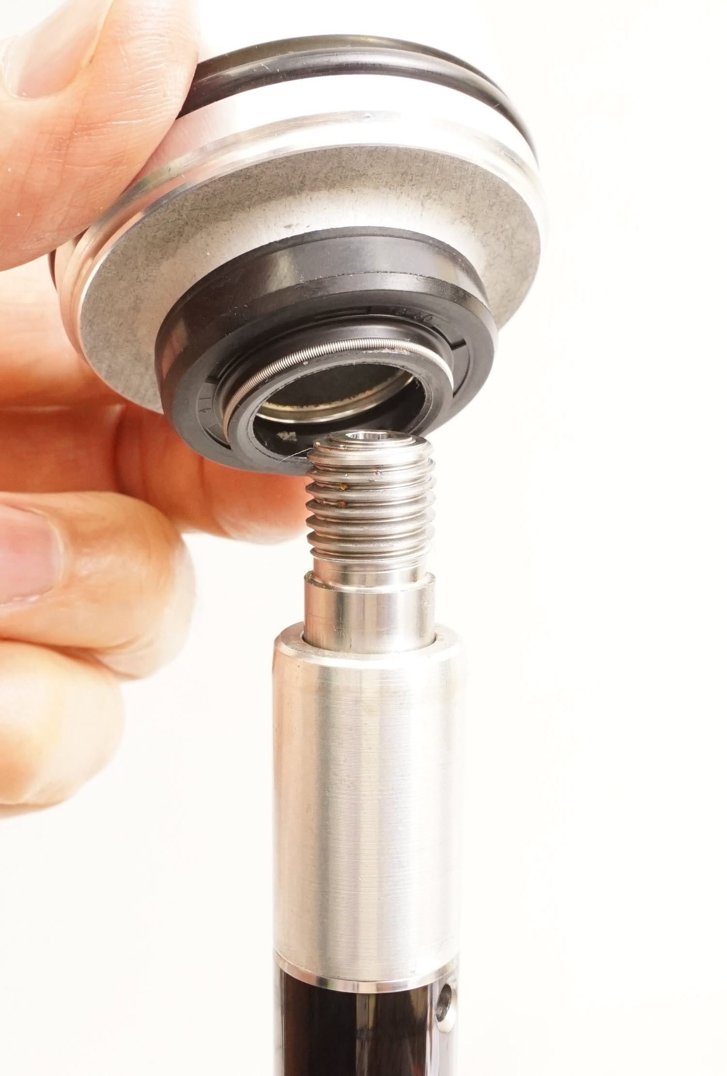
SH1 - This is only required if replacing a seal or shaft bushing. Shock Seals can last a long time but it is a good practice to replace both the Shaft Seal and Dust Seal together if they are over a year old.
|
||||||
|
|
SHAFT ASSEMBLY
SA1 - Install the bumper cup, bumper, and body cap. |
||||||
|
|
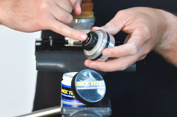
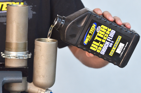
SA2 - Lube the seal with Ultra Slick Grease (USSG 01).
|
||||||
|
|
|||||||
|
|
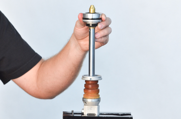
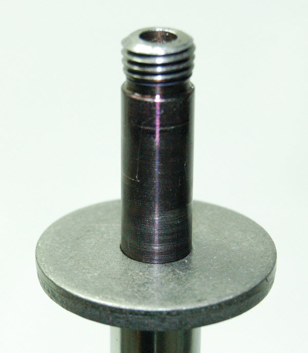
SA4- Install the Base Plate on the Shaft.
There are models that require 2 or even 3 Base Plates to create the correct Total Valve Stack Height. The original Base Plate goes on first. Any additional Base Plates or Spacing Shims go on next. See step V8.
Note - Some shocks with a top-out spring use a shim under the Base Plate. If your shock has this configuration, re-install the shim first.
|
||||||
|
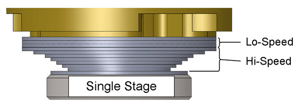
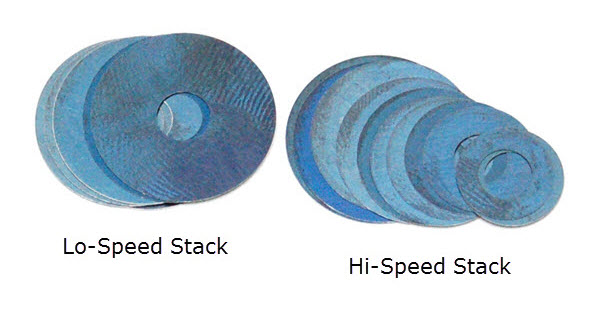
VALVING STACK TYPES - SINGLE OR TWO STAGE
V2- You will either be building a Single Stage or a Two Stage Stack (or possibly a combination of both). The difference is the Crossover. The Crossover is a smaller diameter shim between the Lo-Speed and the Hi-Speed Stacks. Note: The DVS Custom Setup Sheet displays individual shims and does not label Hi-Speed, Crossover, and Lo-Speed. This is for your information only. Also you will not use all the shims provided in the Gold Valve Kit.
|
|||||||
|
|
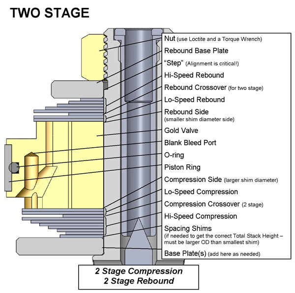
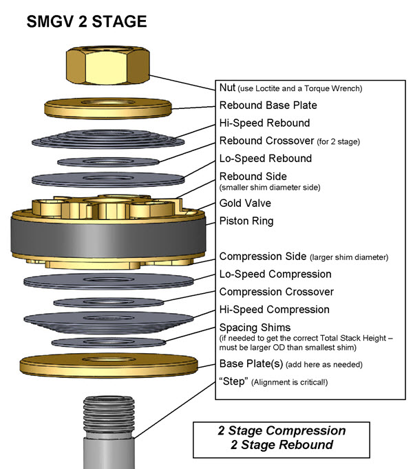
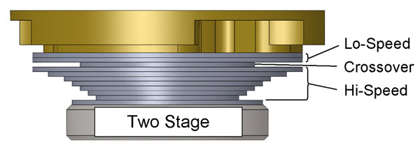
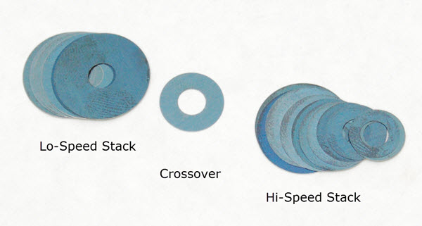
V3- Two Stage Example
(Single Stage is exactly the same except there is no Crossover) For Two Stage the total valving stack is made up of a:
Lo-Speed Stack
Crossover and a
Hi-Speed Stack
(this is only an example - not your setting)
The Total Valving Stack starting from the Gold Valve piston face:
(4) .20x44 - Lo- Speed Stack
(1) .15x28 - Crossover (notice the smaller diameter) (1) .25x44 - Hi- Speed Stack
(1) .25x42 (1) .25x40
(1) .25x38
(1) .25x36
(1) .30x34
(1) .30x32
(1) .30x30
(1) .30x28
(1) .30x26
(1) .30x24
(1) .30x22
|
||||||
|
|
V4 - Install the compression valving stack in the reverse order that it is listed, starting with the last (smallest diameter) shim of the Hi-Speed Compression Stack directly on the Base Plate and ending with the largest diameter shim of the Lo-Speed Compression Stack.
|
||||||
|
|
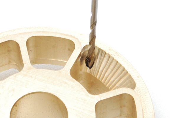
V5- BLEED HOLE (or no bleed hole)
If the DVS does not call for a Bleed Hole (it says "n/a" for Bleed) skip this step.
If your DVS Setup Sheet calls for a Bleed Hole, drill it to the recommended size. To make drilling the Bleed Hole easier, most Gold Valves have a blank pilot hole or holes.
How many holes? - The DVS tells how many Bleed Holes to drill. Most of the time it is one. If there is a number in parenthesis before the hole size this is the quantity i.e. (2)1.3mm (#53) means two bleed holes. Otherwise the quantity is one.
|
||||||
|
|
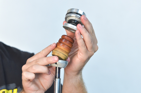
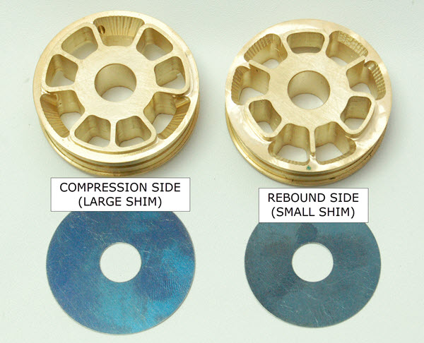
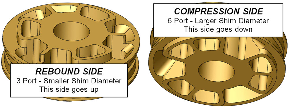
V6- Install the Gold Valve with the compression side of the piston (larger shims) facing down towards the compression valving stack.
The rebound side of the piston (smaller shim side) is shown on the right. The rebound side will face upwards. Note the compression side on the left has larger ports and uses larger diameter shims than the rebound side.
|
||||||
|
|
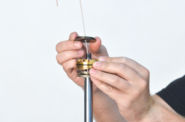
V7- Install the Rebound Valving Stack in the order listed starting with the largest diameter shim and ending with the smallest diameter shim.
|
||||||
|
|
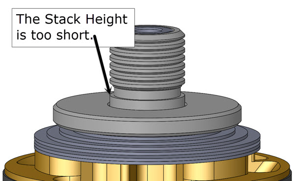
V8- Make sure the Total Valving Stack Height is correct. Critical!!
This step is here to insure you don't "run out of thread" onto the straight, non-threaded, portion of the shaft when tightening the Nut and the Nut gets full engagement.
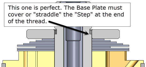
The shims should be guided with the straight, non-threaded part of the shaft and should not be on the thread. The Rebound Base Plate should cover or "straddle" the "step" at the end of the thread.
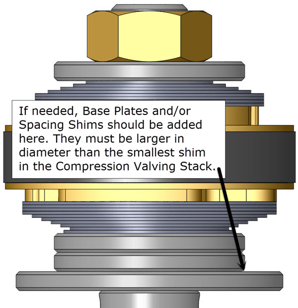
If needed, height adjustment is done with Spacing Shims added just below the Reboud Base Plate.
Spacing Shims must be larger in diameter than the smallest shim in the stack. Sometimes this is best accomplished by adding additional Base Plates.
Click images to enlarge.
|
||||||
|
|
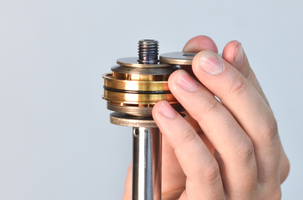
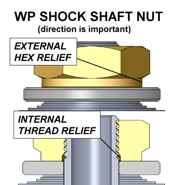
V8a- WP Shock Shaft Nuts
WP Shock Shaft Nuts can be slightly different. The ones that have an External Hex Relief usually have a 2mm Internal Thread Relief. This means the end of the thread can be as much as 1mm above the Base Plate when installed.
Be very careful not to run out of thread. Use Loctite and a Torque Wrench.
|
||||||
|
|
V9- Make sure you select the proper nut. In many Gold Valve Kits more than one thread pitch nut is included and sometimes the stock nut is reused.
Ohlins, Sachs, and WP shocks reuse the stock nut.
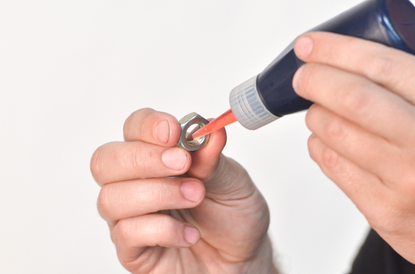
Clean everything completely. Use Hi-Strength Loctite (included) on the shaft nut.
|
||||||
|
|
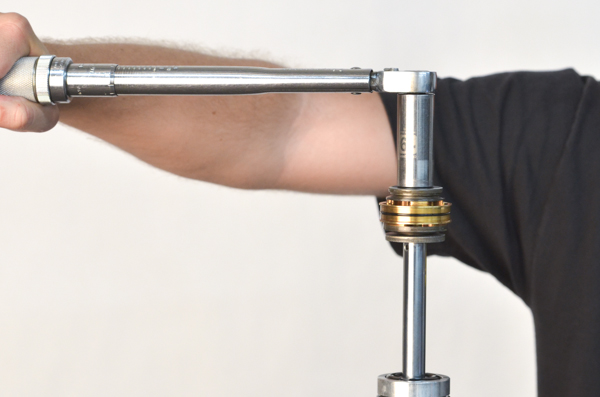
V10- Install and torque the shaft nut to the proper setting (see the DVS) using a torque wrench. This is critical!
|
||||||
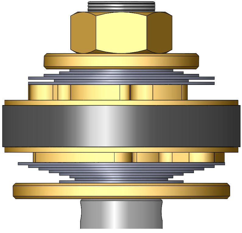
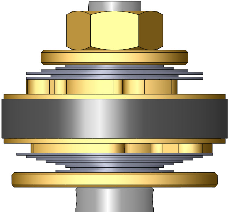
| V11- Single Stage Compression and Rebound
|
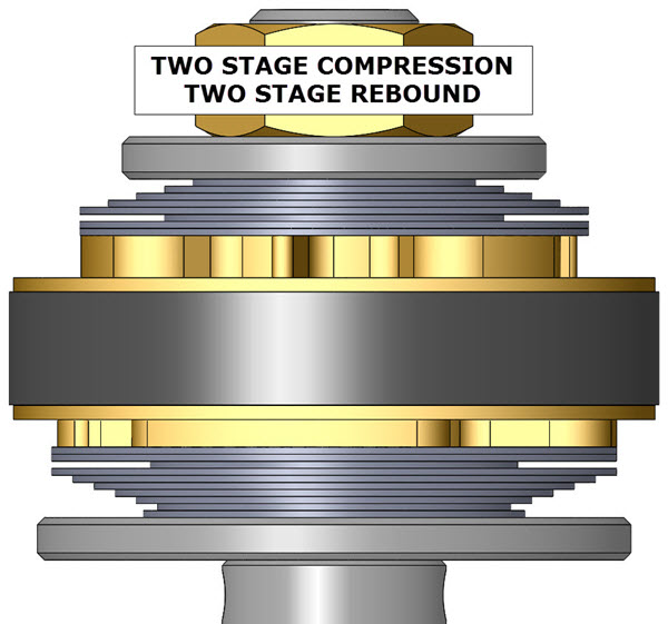
V11- Two Stage Compression and Rebound
|
||||||
|
|
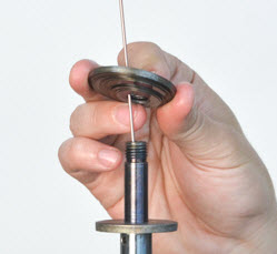
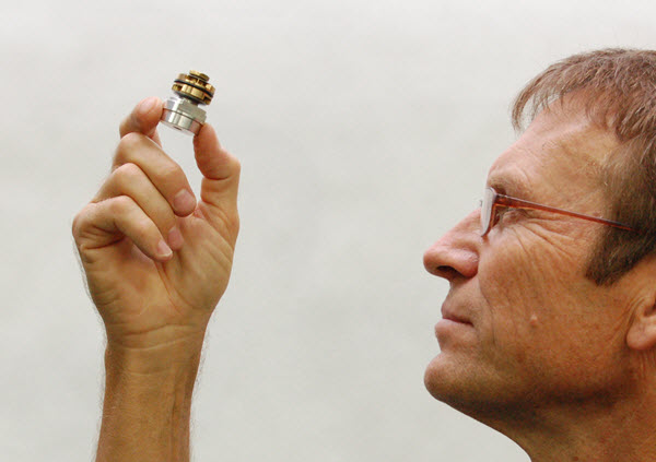
V12- Visually check your work.
Hold the completed valving assembly up to the light and look for any irregularities. Make sure the shims are laying flat on the piston surface. On two stage stacks check that the Crossover Gap is clearly visible.
If there are any problems, disassemble the stack and look for dirt, bent shims, or any other causes. Reassemble and inspect again.
You might be thinking that this looks like either a very tiny shock shaft or a fork compression valve. Well, you're right, it's a very tiny shock shaft. You get the idea.
|
||||||
|
|
V13- Make sure the shims that go next to the Gold Valve completely cover the ports on both sides of the piston! If the ports are not covered there will not be enough damping.
This could be caused by a number of reasons. Piston upside down, Compression and Rebound Stacks reversed on location or installed upside down.
Please call Tech Support if this occurs and you can't figure it out.
|
||||||
|
|
V14- Return to the main Rebuild instructions to complete the reassembly.
|
||||||


| • Single Stage - made of: Lo-Speed Stack Hi-Speed StackThere is NO Crossover (it becomes one stack.) |
 |
 |
| • Two Stage - made of: Lo-Speed Stack Crossover Hi-Speed StackThe Crossover Gap is visible |
 |
 |
Color Presets