Shock Gold Valve InstallationVALVING WP PDSThese instructions cover installation of the Shock Gold Valve onto the shaft for WP PDS shocks. To get to this point in the installation see the ►General WP PDS shock rebuild instructions ClickHere. Some SMGV 4633 kits are for standard shocks, not PDS. Valving instructions for standard Shocks ►ClickHere. Click on the images to enlarge. Shortcuts: > SHAFT DISASSEMBLY CAUTION: IF YOU ARE UNFAMILIAR WITH REBUILDING AND REVALVING SHOCKS, STOP!!! DO NOT PROCEED; SEEK OUT A QUALIFIED SUSPENSION TECHNICIAN. NOTE: All measurements are metric (for inches divide by 25.4). The valving list starts at the piston face and goes towards the Base Plate. Valve specs are listed by (QUANTITY) THICKNESS x DIAMETER. A number in parentheses means quantity. If there is no number in parenthesis the quantity is one. Example: (2).15x30 means quantity two, 15 hundredths of a millimeter thick by 30 millimeters in diameter. |
|||||||
|
|
Tools
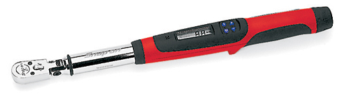
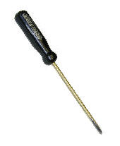
- Torque wrench (SnapOn Digital Torque Wrench shown) - Metric calipers and micrometer
- TMVJ 065 Vise Jaws mounted on a Vise - suggested - TSSB Series Bullet Tool - for Seal Head installation Supplies
Contact Cleaner - or other good, clean solvent
Loctite - Hi-Strength (included in the Gold Valve Kit)
USSG 01 - Ultra Slick Seal Grease
|
||||||
PDS SHOCK TYPESThere are 3 types of WP PDS Shocks: Type 1 - Mono Shaft - 1999 thru 2008 - SMGV 5046 Type 2 - Secondary Piston Holder - 2009 thru current - SMGV 5042 Type 3 - Dual Diameter Piston - used on KTM 85 SX models - SMGV 4633 |
|||||||
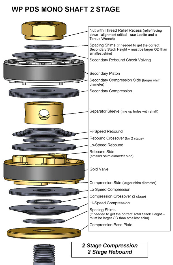
TYPE 1 - MONO SHAFT
|
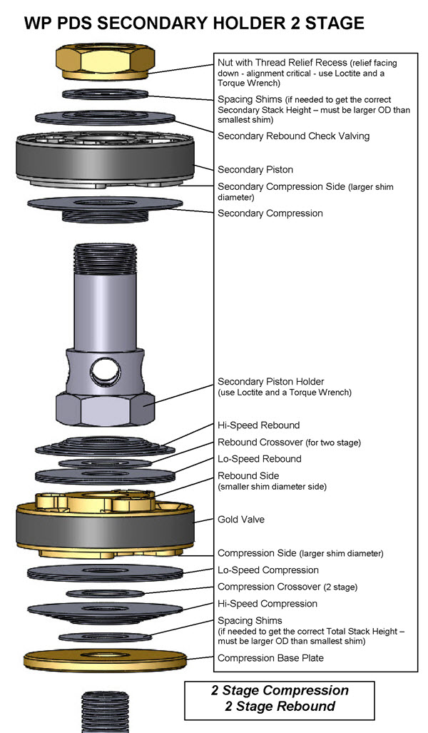
TYPE 2 - SECONDARY HOLDER
|
||||||
|
|
|||||||
|
|
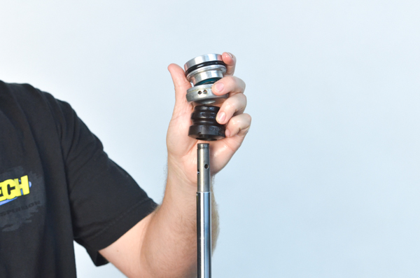
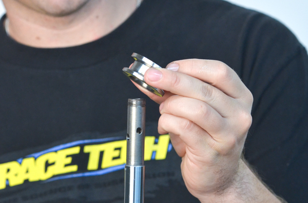
SD2 - Remove the shock shaft nut. Notice that it is directional (there is an up and a down.) On the inside at the bottom there is thread relief.
|
||||||
|
|
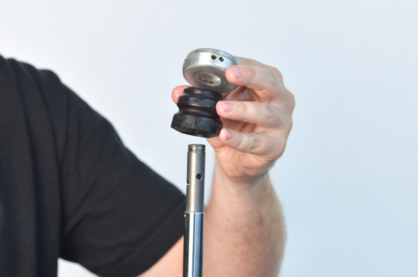
SD3 - Remove the valving stack.
This is a Type 1 Mono Shaft early model shock where both pistons are on the main shaft.
On later models (Type 2 and 3) the Secondary Piston is held with a Secondary Piston Holder that threads onto the main shaft. This Piston Holder acts as the Nut for the Primary Piston Assembly.
|
||||||
|
|
SD4 - Remove the seal head, body cap and bottom-out bumper.
Inspect the Bottom-out Bumper for tears or damage. Bumpers are wear items. They break down over time and should be replaced when any signs of deterioration exist.
Bumpers available at Race Tech.
|
||||||
|
|
SH1 - This is only required if replacing seals or shaft bushings. Shock Seals can last a long time but it is a good practice to replace both the Shaft Seal and Dust Seal together if they are over a year old.
|
||||||
|
|
|||||||
|
|
SA2 - Grease the seal with Ultra Slick Grease.
|
||||||
|
|
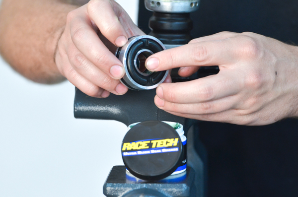
SA3 - Reinstall the seal head with a Shock Seal "Bullet" Tool (TSSB Series).
|
||||||
|
|
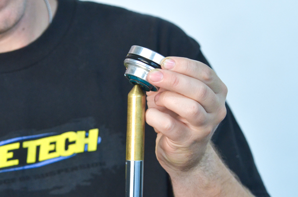
SA4 - Install the base plate. In this case this is a lowering base plate used for Supemoto.
|
||||||
|
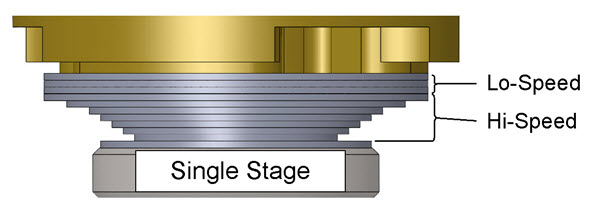
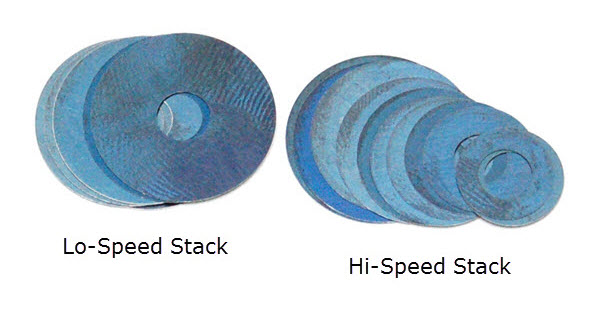
VALVING STACK TYPES - SINGLE OR TWO STAGE
V2- You will either be building a Single Stage or a Two Stage Stack (or possibly a combination of both). The difference is the Crossover. The Crossover is a smaller diameter shim between the Lo-Speed and the Hi-Speed Stacks. Note: The DVS Custom Setup Sheet displays individual shims and does not label Hi-Speed, Crossover, and Lo-Speed. This is for your information only. Also you will not use all the shims provided in the Gold Valve Kit.
|
|||||||
|
|
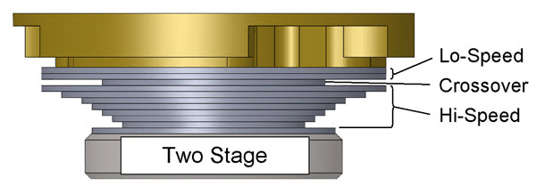
V3- Two Stage Stacks
(Single Stage is exactly the same except there is no Crossover) Note - Single vs. Two Stage only applies to the Primary Piston.
For Two Stage the total valving stack is made up of a:
Lo-Speed Stack
Crossover and a
Hi-Speed Stack
(this is only an example - not your setting)
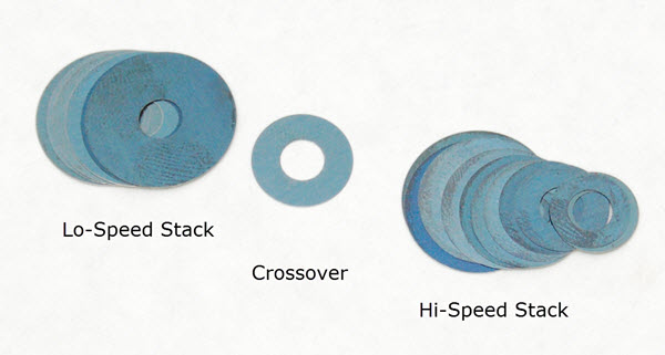
The Total Valving Stack starting from the Gold Valve piston face:
(4) .20x44 - Lo- Speed Stack
(1) .15x28 - Crossover (notice the smaller diameter) (1) .25x44 - Hi- Speed Stack
(1) .25x42 (1) .25x40
(1) .25x38
(1) .25x36
(1) .30x34
(1) .30x32
(1) .30x30
(1) .30x28
(1) .30x26
(1) .30x24
(1) .30x22
|
||||||
|
|
V4 - Install the compression valving stack in the reverse order that it is listed, starting with the last (smallest diameter) shim of the Hi-Speed Compression Stack directly on the Base Plate and ending with the largest diameter shim of the Lo-Speed Compression Stack.
Shown is one of the Type 1 early style mono shafts used commonly through about 2008. In 2009 WP introduced a Type 2 two-piece shaft which allows the use of a much larger ID valve improving flow dramatically.
|
||||||
|
|
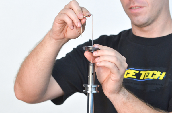
V5- BLEED HOLE (or no bleed hole)
If the DVS does not call for a Bleed Hole (it says "n/a" for Bleed) skip this step.
If your DVS Setup Sheet calls for a Bleed Hole, drill it to the recommended size. To make drilling the Bleed Hole easier, most Gold Valves have a blank pilot hole or holes.
How many holes? - The DVS tells how many Bleed Holes to drill. Most of the time it is one. If there is a number in parenthesis before the hole size this is the quantity i.e. (2)1.3mm (#53) means two bleed holes. Otherwise the quantity is one.
Secondary Pistons NEVER have a Bleed Hole.
|
||||||
|
|
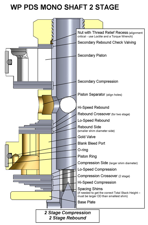
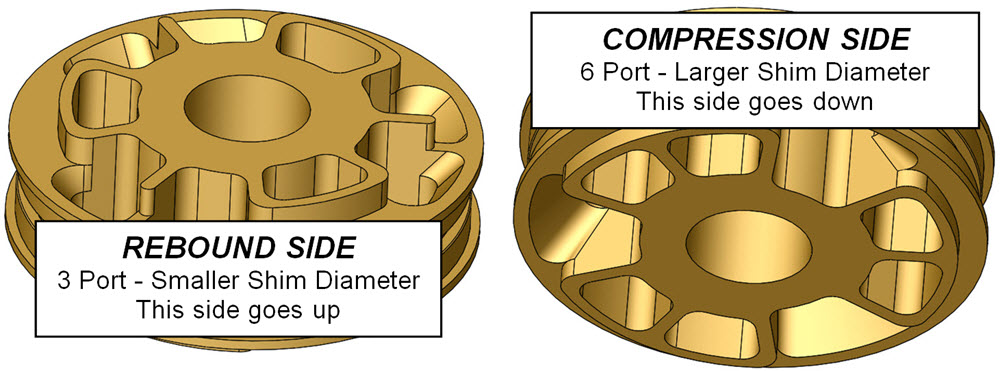
V6- Install the Gold Valve with the compression side of the piston (larger shims) down towards the compression valving stack.
The rebound side of the piston (smaller shim side) is shown on the right. Note the compression side on the left has larger ports and uses larger diameter shims than the rebound side.
|
||||||
|
|
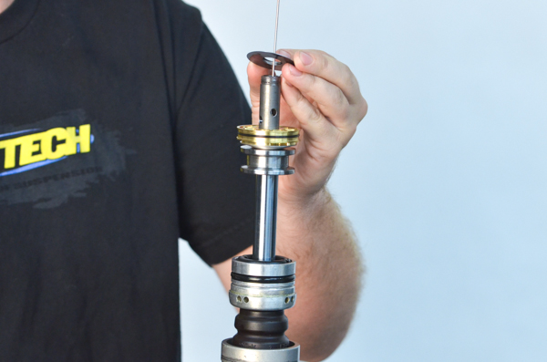
V7- Install the Primary Rebound Valving Stack in the order listed starting with the largest diameter shim and ending with the smallest diameter shim.
|
||||||
|
V8- Make sure the Total Valving Stack Height is correct. Critical!!
PDS SHOCK TYPESThere are 3 types of WP PDS Shocks: Type 1 - Mono Shaft - 1999 thru 2008 - SMGV 5046 Type 2 - Secondary Piston Holder - 2009 thru current - SMGV 5042 Type 3 - Dual Diameter Piston - used on KTM 85 SX models - SMGV 4633 Identify your Type and see it's section for further detail.
|
|||||||
|
|
V9-TYPE 1
PRIMARY VALVING STACK SETUP
Even though both pistons are on the same shaft the Primary Valve Stack Height is important. The top of the Primary Rebound Stack must not cover the feed holes in the shaft.
See V10-TYPE 1
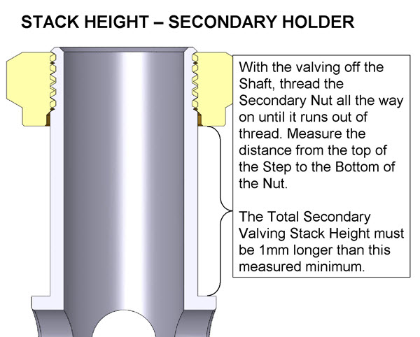
SECONDARY VALVING STACK SETUP
You must measure the available travel for the Nut.
The shims should be guided with the straight, non-threaded part of the shaft and should not be on the thread.
The nut must not run out of thread onto the straight portion of the shaft.
See V14-TYPE 1
|
||||||
|
|
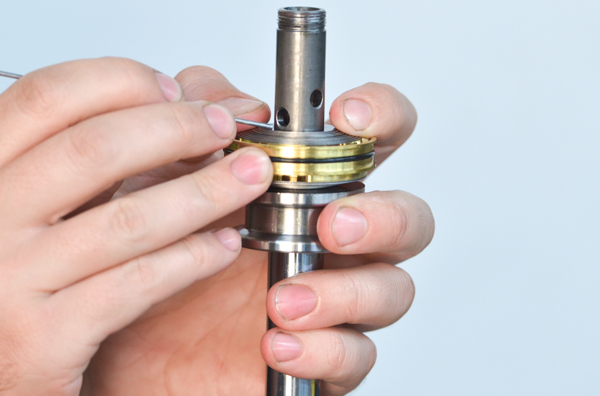
V10-TYPE 1- On Type 1 (early) Mono Shaft Shocks, make sure the height of the Primary Rebound Stack is below the feed holes in the shaft.
|
||||||
|
|
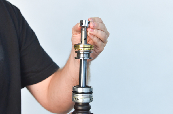
V11-TYPE 1- Insert the Separator Sleeve between the primary and secondary valving.
|
||||||
|
|
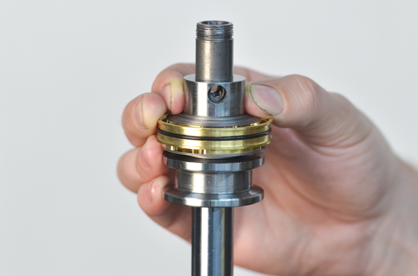
V12-TYPE 1- Align the holes in the sleeve with the holes on the shaft.
|
||||||
|
|
V13-TYPE 1- Install the Secondary Compression Valving starting with the smallest diameter shim and ending with the largest. Install the Secondary Piston with the compression (larger shim) side of the piston facing downward.
Reinstall the stock Secondary Rebound Valving/Check Valving on the shaft.
|
||||||
|
|
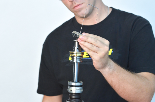
V14-TYPE 1- Make sure the Total Valving Stack Height is correct. Critical!!
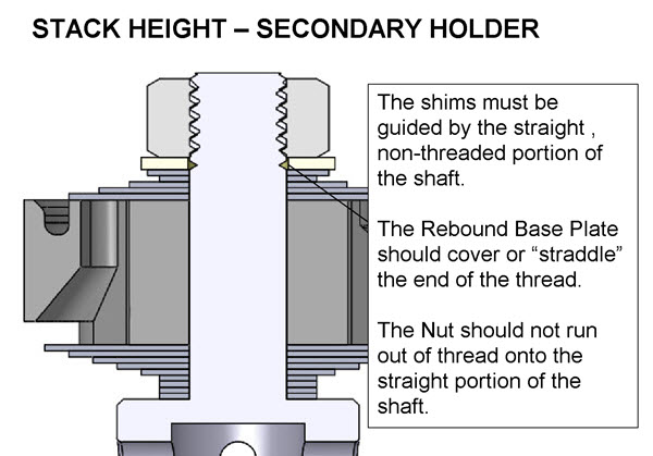
The shims should be guided with the straight, non-threaded part of the shaft and should not be on the thread.
The nut must not run out of thread onto the straight portion of the shaft.
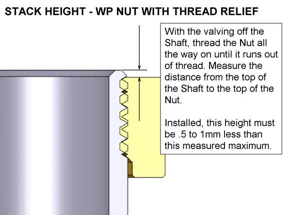
With the valving off the Shaft, thread the Nut all the way on until it runs out of thread. Measure the distance from the top of the Shaft to the top of the Nut.
Installed, this height must be .5 to 1mm less than this measured maximum.
This height adjustment is done with Spacing Shims. If needed, they should be added just below the Nut.
Spacing Shims must be larger in diameter than the smallest shim in the stack.
|
||||||
|
|
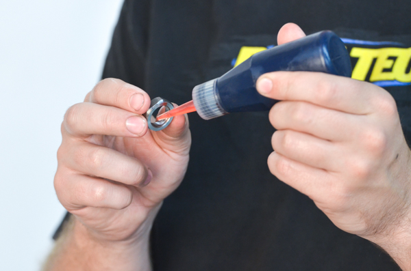
V15-TYPE 1- Apply Loctite to the shaft nut and install it. It is directional. There is a thread recess on the bottom side. It is critical the Total Valve Stack Height is correct.
|
||||||
|
|
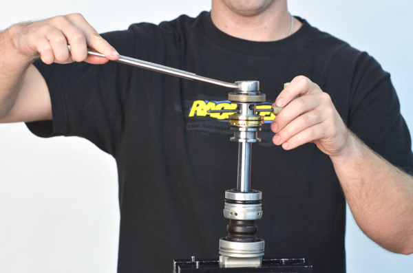
V16-TYPE 1- When reassembling the valving assembly, position the spacer so the feed ports on the sleeve are aligned with the ports on the shaft while the shaft nut is torqued.
Install and torque the shaft nut to the proper setting (see the DVS) using a torque wrench. Use Loctite. This is critical!
Double check the Nut to End-o-Shaft Height.
|
||||||
|
|
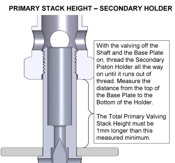
V17-TYPE 2
This type uses a Secondary Piston Holder. Both the Primary and the Secondary stacks must be setup independently.
PRIMARY VALVING STACK SETUP
|
||||||
|
|
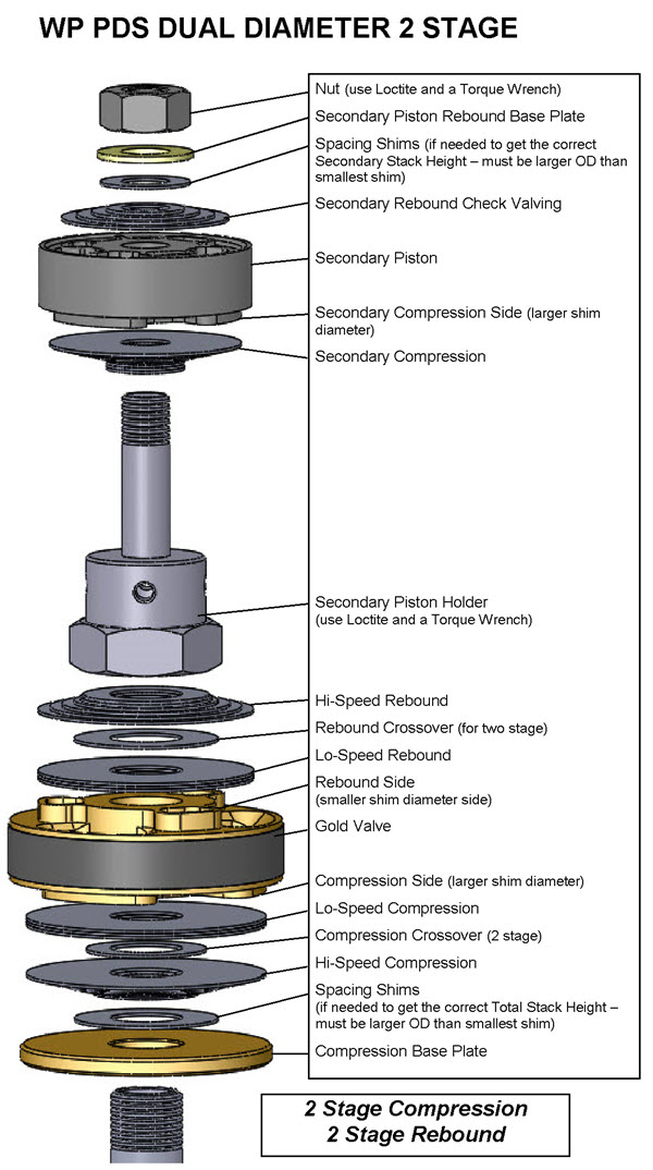
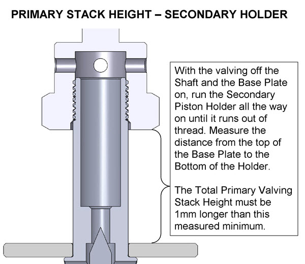
V18-TYPE 3
This type uses a Secondary Piston Holder. The Secondary Piston is smaller in diameter than the Primary. Both the Primary and the Secondary stacks must be setup independently.
PRIMARY VALVING STACK SETUP
|
||||||
| V19- Single Stage Compression and Rebound (shown on a non-PDS shock)
|
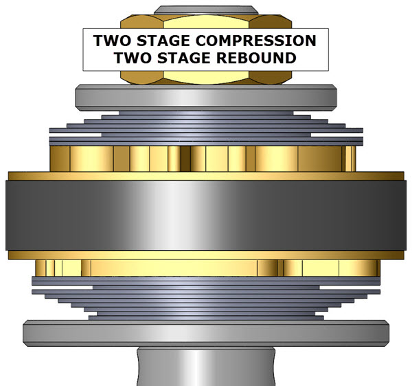
V19- Two Stage Compression and Rebound (shown on a non-PDS shock)
|
||||||
|
|
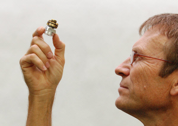
V20- Visually check your work.
Hold the completed valving assembly up to the light and look for any irregularities. Make sure the shims are laying flat on the piston surface. On two stage stacks check that the Crossover Gap is clearly visible.
If there are any problems, disassemble the stack and look for dirt, bent shims, or any other causes. Reassemble and inspect again.
You might be thinking that this looks like either a very tiny shock shaft or a fork compression valve. Well, you're right, it's a very tiny shock shaft. You get the idea.
|
||||||
|
|
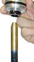
V21- Make sure the shims that go next to the Gold Valve completely cover the ports on both sides of the piston! If the ports are not covered there will not be enough damping.
This could be caused by a number of reasons. Piston upside down, Compression and Rebound Stacks reversed on location or installed upside down.
Please call Tech Support if this occurs and you can't figure it out.
|
||||||
|
|
V22- Return to the main Rebuild instructions to complete the reassembly.
|
||||||


| • Single Stage - made of: Lo-Speed Stack Hi-Speed StackThere is NO Crossover (it becomes one stack.) |
 |
 |
| • Two Stage - made of: Lo-Speed Stack Crossover Hi-Speed StackThe Crossover Gap is visible |
 |
 |