SHOCK ASSEMBLY ONLY
|
|
|
|
OVERVIEW
The most important thing to remember is the Nitrogen Reservoir is a Nitrogen Reservoir - not an Oil Reservoir.
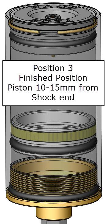
When the shock is complete the Reservoir Piston should be 10-15mm from the shock end of the reservoir. This means it is mostly filled with Nitrogen, not oil.
If you put too much oil in the shock, the reservoir piston will be too close to the nitrogen end. If this happens, you might destroy the shock if it runs out of travel on the compression stroke.
|
|
|
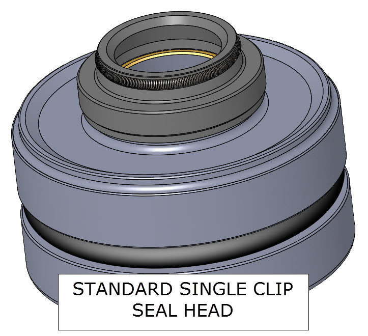
STANDARD SINGLE CLIP SEAL HEADS
The second thing to be aware of is the type of Seal Head you have. Most modern Standard Seal Heads are an a held in with one circlip. The Seal Head displaces oil when installed into the shock body.
This oil displacement automatically moves the Piston to the correct Finished Position.
|
|
|
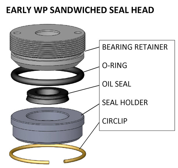
SANDWICHED SEAL HEADS
If the Seal Head is assembled in place in the shock body, it will not displace oil during assembly. Therefore the Piston must be located in Position 3 - Finished Position (10-15mm from the shock body end) before installing the seal.
This applies to early WP shocks, early Ohlins 36mm dual shocks, and most early (pre-1983) Yamaha (Soqi) shocks.
Note - Yamaha 2-clip Seal Heads can be replaced with a single clip design RT Seal Head (SYSH 461413). Single clip seal heads are also available for the early 36mm Öhlins. See the Product Search. Once this is done, follow the procedure for Standard Single Clip Seal Heads.
|
 |
|
|
|
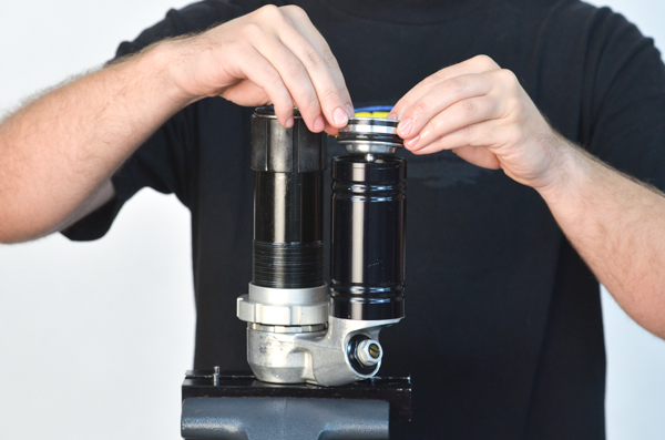
A2 - Open End Reservoir - If the end of the reservoir is open, fill the reservoir with oil. Installing the Piston should make the reservoir overflow. This is so no bubbles are trapped inside.
Push the piston down until the band engages the reservoir. The oil should be overflowing at this point.
|
|
|
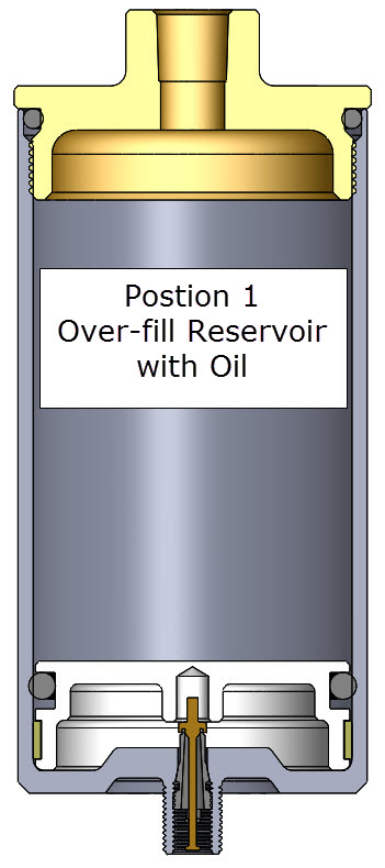
A3 - Closed End Reservoir - If the Nitrogen end of the Reservoir is closed (at the bottom of the illustration below), push the Reservoir Piston down to the nitrogen end (Position 1) with either air pressure or a blunt rod like a #3 Phillips Screwdriver. Then fill it with oil.
If it is a remote reservoir attached with a hose it may be easiest to remove the Hose and pour the oil in. Fill the reservoir with oil.
Re-attach the reservoir hose after filling. If the hose is long, fill the hose before attaching by putting oil in the shock body and holding the end of the hose below the oil level in the body. Oil will flow out. Quickly attach the hose to the reservoir.
|
|
|
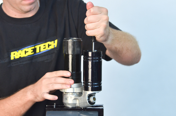
A4 - Open-End - Invert the shock so any trapped air will be pushed out of the reservoir (not shown). Be sure to catch the fresh oil so you can reuse it. Bleed the air from the reservoir by pushing the piston all the way to the bottom, Position 2 - Bleeding Position.
XXXXXXXX
|
|
|
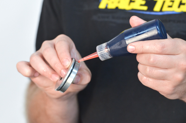
A5 - Open-End - For this WP shock, apply Loctite to the reservoir cap.
|
|
|
A6 - Open-End - WP - Tighten the reservor cap using a Pin Spanner.
|
|
Option 1 |
A7 - To prepare the shock for bleeding pressurize the Reservoir to 20-40 psi.
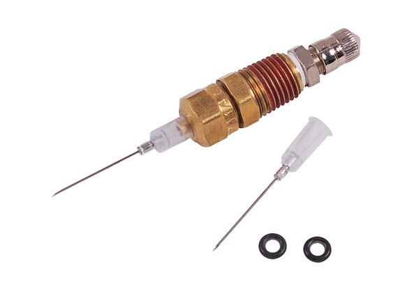
KYB, Ohlins, Sachs, early Yamaha, etc. use either a Schrader or a TSNN 01 Nitrogen Needle to pressurize the Reservoir.
WP - There are five choices for charging WP shocks.
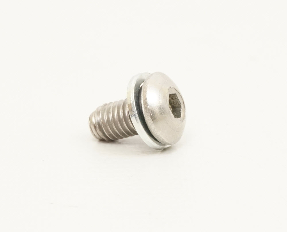
Option 1 - Use a SPNV 0512 Nitrogen Charging Bolt and a TSNN 01 Nitrogen Needle.
Option 2 - Replace the reservoir with a Bladder Conversion Kit (SWBL Series). Many riders swear by this mods added plushness.
Option 3 - Use a TSNC 02 WP Charging Tool with the stock hardware. (If you are doing a lot of shocks this one really pays off.)
Option 4 - Use the official WP charging tool with the stock hardware.
Option 5 - Drill and tap the reservoir cap to 1/8" NPT and install a Schrader "Tank" Valve. You must be careful as on some models the swingarm will break off the Schrader at full bottom-out.
|
|
|
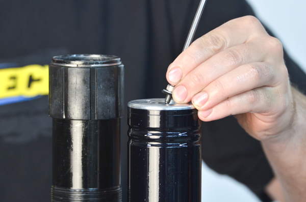
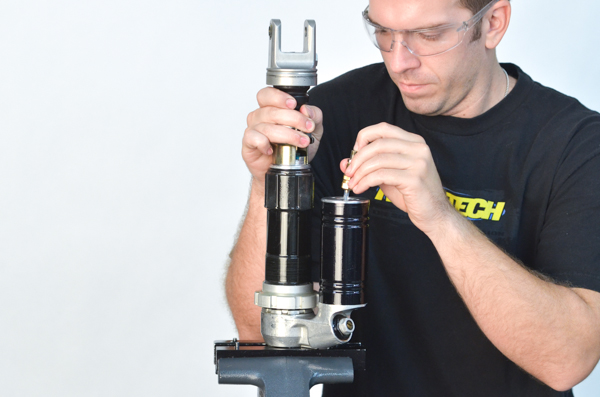
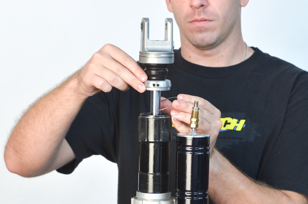
A8 - WP Option 1, install a Nitrogen Charging Bolt (SPNV 0512), into the reservoir cap.
|
|
|
|
|
|
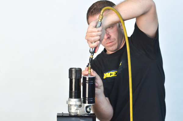
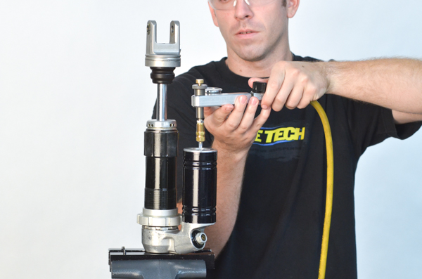
A10 - pressurize the reservoir to 20 to 40 psi. A rubber tipped blow gun usually works great.
This moves the piston to Position 2, the Bleeding Position (all the way to the Shock Body end of the reservoir). It also forces oil and air bubbles out through the Compression Adjuster.
|
|
|
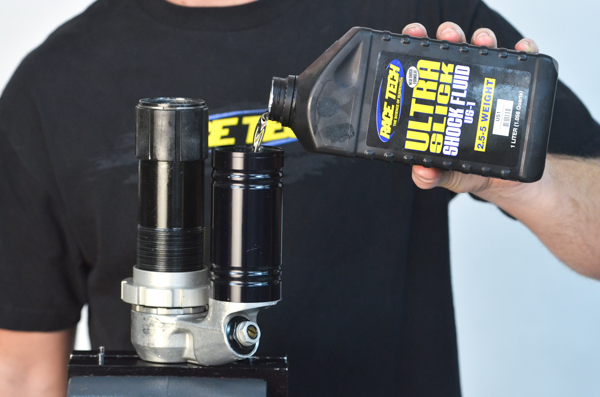
A11 - Add oil in the shock body up to about 50mm from the top.
|
|
|
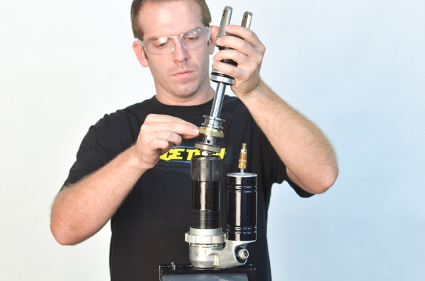
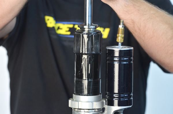
A12 - Install the shaft assembly into the shock body.
|
|
|
A13 - The oil will overflow.
|
|
|
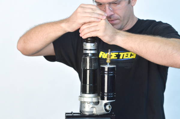
A14 - To bleed the shock, rapidly and forcefully compress the shock shaft.
|
|
|
A15 - Extend the shock shaft slowly to avoid cavitation.
Repeat as necessary until there are no more bubbles.
|
|
|
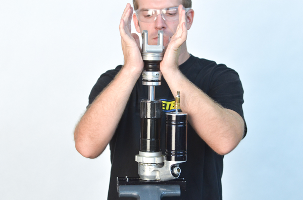
A16 - Use the Shock Seal Head Setting Tool and...
|
|
|
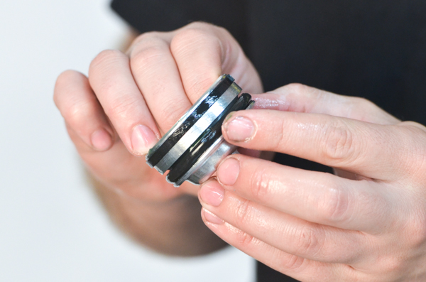
A17 - push the Seal Head into the body while releasing nitrogen from the reservoir.
With a Standard Single Clip Seal Head (non-sandwiched) this step moves the Reservoir Piston from Position 2 - Bleeding to Position 3 - Finished automatically.
- With a Sandwiched Seal Head the Reservoir Piston MUST be located at Position 3 - Finished Position BEFORE the Seal is installed in its Holder.
|
|
|
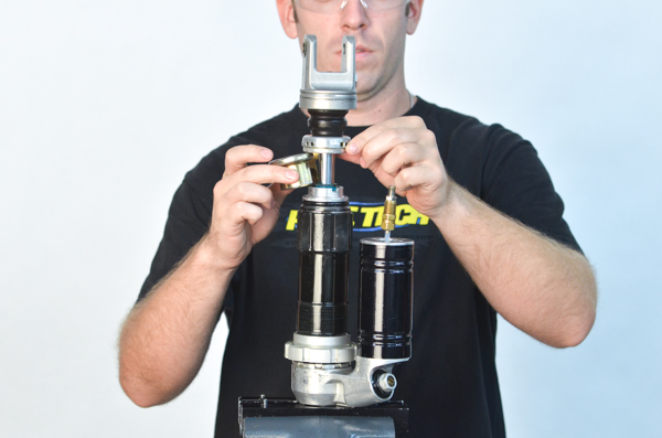
A18 - Install the circlip making sure the clip is fully seated in the groove.
|
|
|
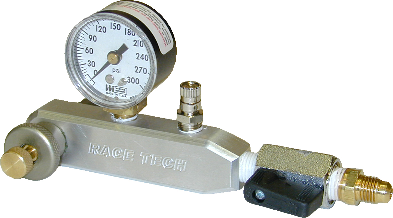
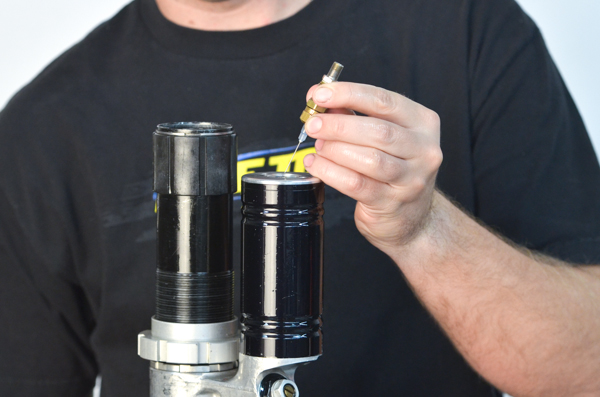
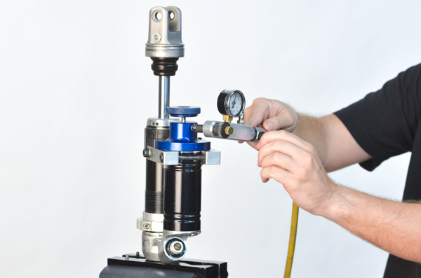
A19 - Pressurize the shock, in this case (with a SPNV 0512), using a TSNN 01 Nitrogen Needle and TSNG 02 Nitrogen Gauge.
|
|
|
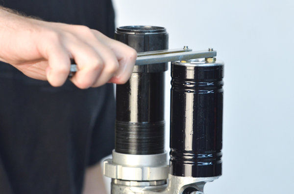
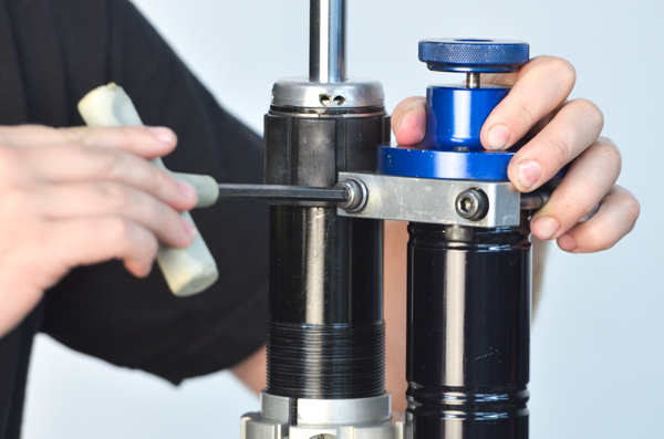
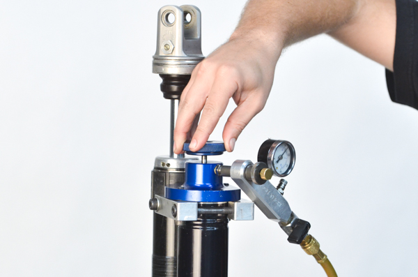
A20 - WP Option 3 - Another option to pressurize a WP Shock is to use a RT WP Nitrogen Charging Tool (TSNC 02). Push down on the tool and tighten the clamp bolts.
|
|
|
A21 - Charge the reservoir with nitrogen to the recommended pressure.
|
|
|
A22 - Tighten down the allen bolt with the large knob and remove the tool.
|
|
|
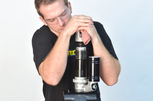
A23 - Compress the shaft and verify that it is charged by watching it return completely.
If it does not return completely, either something is bent (shaft or body) or the Reservoir Piston is not located properly. Likely, it is at Position 2, resting on the Shock Body end of the Reservoir.
|
|
|
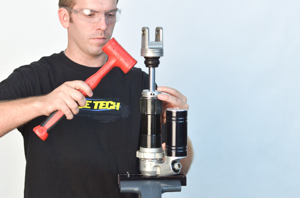
A24 - Install the Pressed-in Body Cap by lightly, and evenly, tapping it with a plastic mallet.
Screwed-in Body Caps, as you might think, get screwed in.
|
|
|
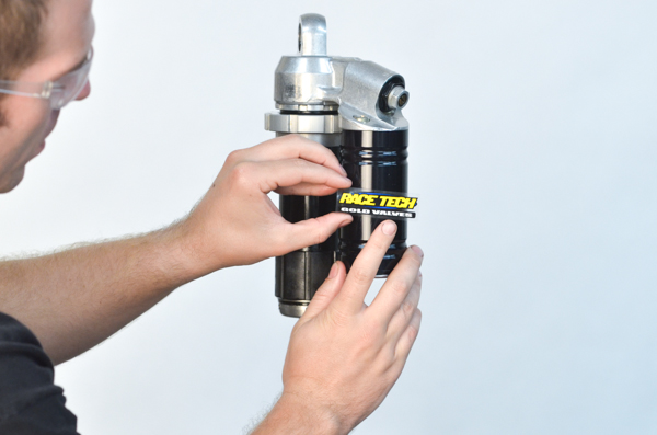
A25 - Install the groovy sticker. Set the clickers, install the spring with the proper preload (see the DVS) and enjoy.
Go ride!
|
With the switch to the new racetech website and systems we are requesting each user reset their password in our system. Simply use our forgot password feature on the login page to reset yours.