SHOCK REBUILD - BFRC SHOWA
|
|
|
|
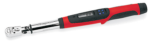
Tools
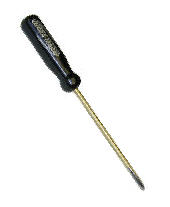
- Torque wrench (SnapOn Digital Torque Wrench shown)
- Metric calipers and micrometer
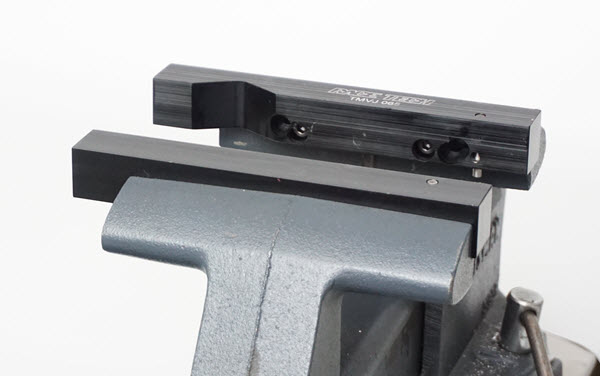
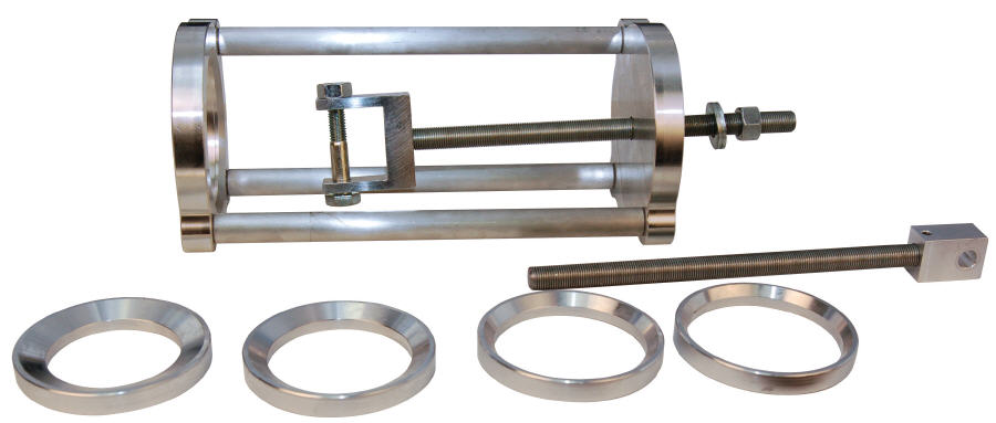
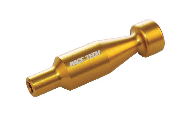
- TMVJ 065 Vise Jaws mounted on a Vise - suggested - TSSB 16 - for Seal Head installation - TSSC 02 - Spring Compressor Screw Type Nitrogen Charging Equipment |
|
|
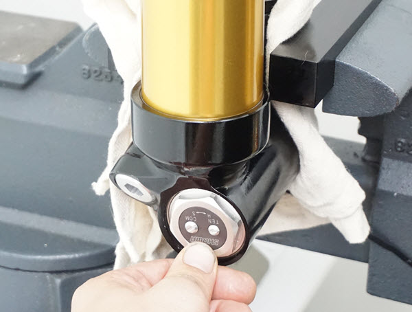
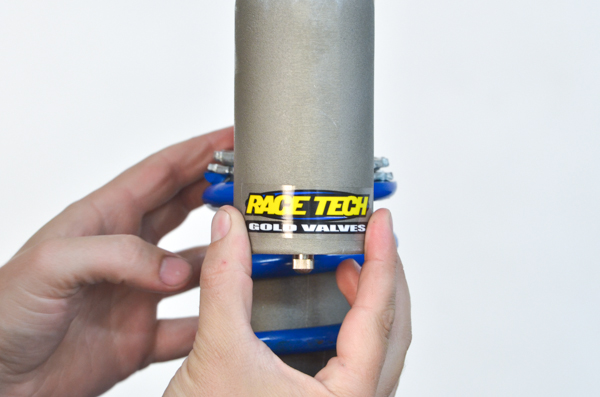
D1 - Place the end of the shock body in a vise, using Aluminum Vice Jaws (TMVJ 065), or secure using the shock eyelet with soft jaws. Be careful not to crush the shock body. Check clicker positions on dampers and note the settings. Back the adjusters out all the way.
Compress the shock and make sure it returns completely. If it does not, there may be a bent shaft, blown shaft seal, a bad bladder, or low-pressure.
|
|
|
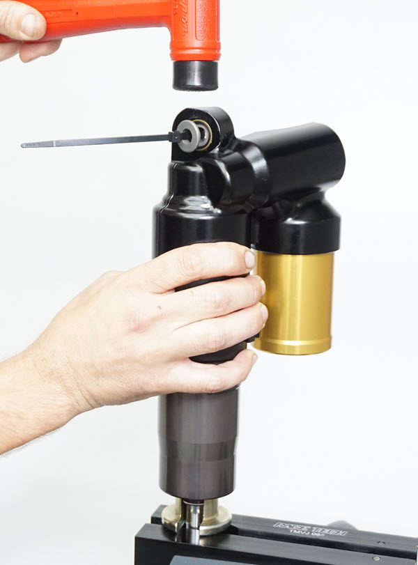
D2 - Remove the valve core. Depress the bladder cap enough to expose the clip. Remove the clip.
If the cap is stuck use a hammer and a socket to protect the valve stem and gently tap the cap down.
|
|
|
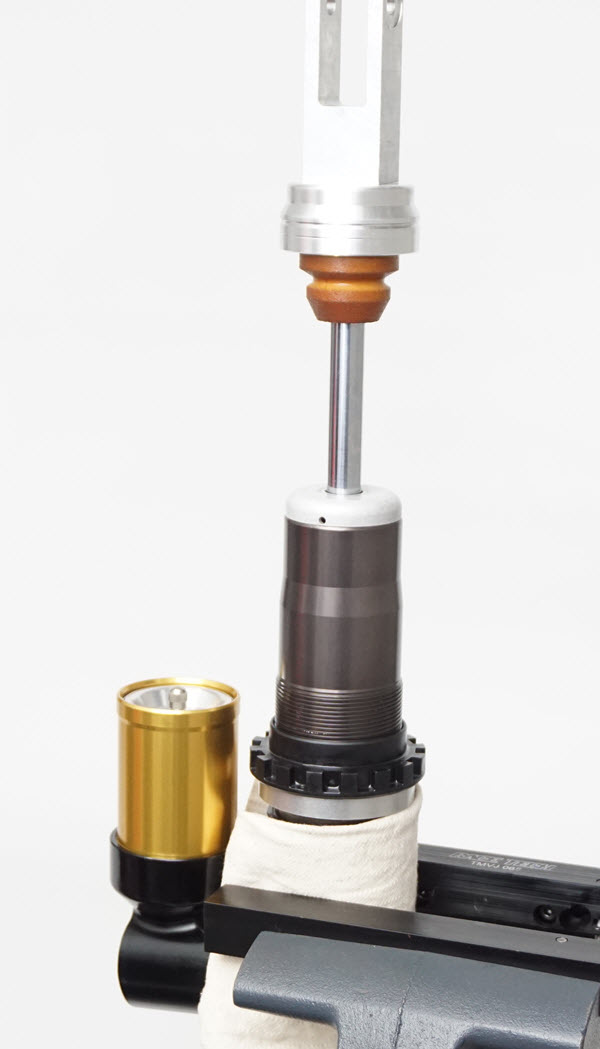
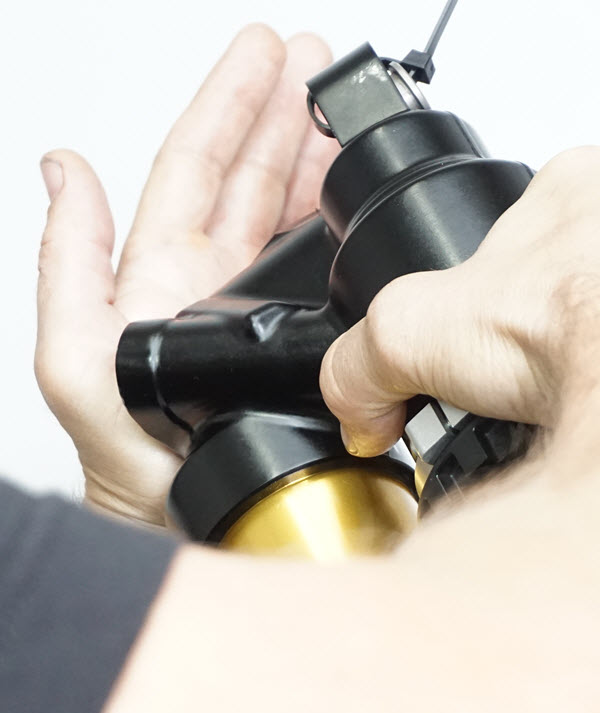
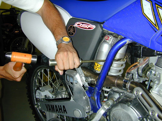
D3 - Remove the reservoir cap. Method 1.
One method is to use a Reservoir Cap Removal Tool (TSCT 01). If you choose this method make sure the tool is screwed on all the way. Pull upwards with only the slightest side to side movement. This is so you don't break off the valve stem.
This is even easier if you depress the shock shaft at the same time.
|
|
|
D4 - Remove the reservoir cap. Method 2.
My favorite method is to use a rubber tipped air gun and use compressed air to blow the cap off. The bladder cap will pop off with a bang.
This seems dangerous but as soon as the bladder pops off all the trapped air is released quickly and the cap doesn't go anywhere. I like to use my free hand and hold a rag over the end of the bladder cap to contain it and the oil.
|
|
|
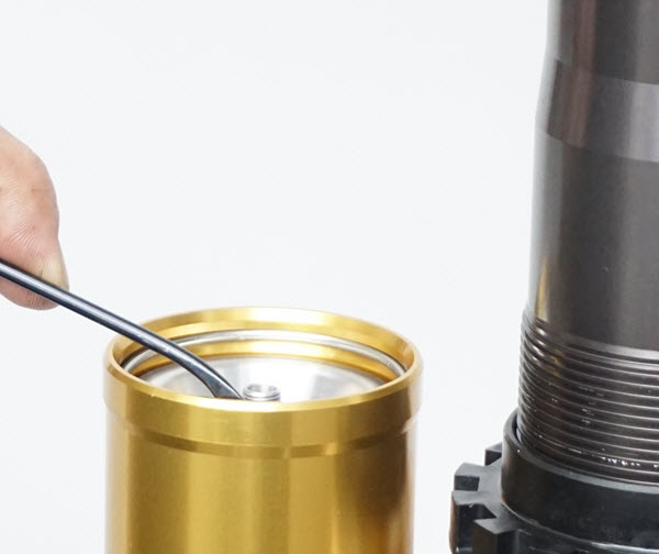
D5 - Remove the shock body cap with a sharp wood chisel at the junction of the cap and the body.
|
|
|
D6 - Compress the seal head into the body with a Seal Head Setting Tool (TSSS Series) to expose the circlip.
|
|
|
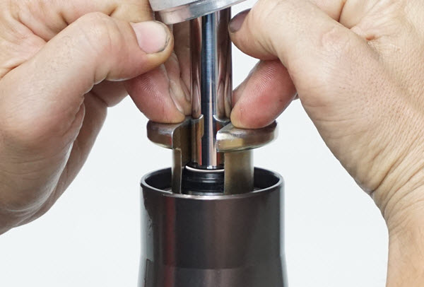
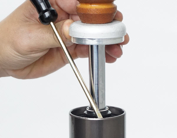
D7 - Remove the seal head circlip with the clip tool. This circlip groove has a large chamfer on the bottom side so all that is needed is to press the clip downward and out of the groove.
|
|
|
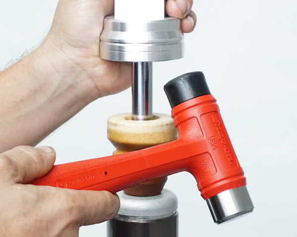
D8 - Remove the shaft assembly from the shock body by tapping upwards with a plastic mallet.
Empty the oil and dispose of properly.
|
|
|
|
|
|
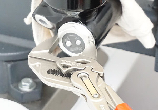
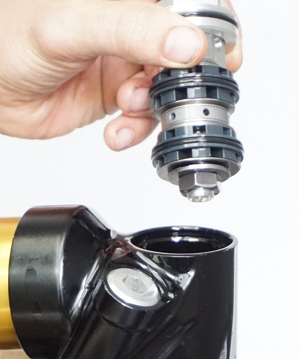
D10 - Remove the Valving Assembly with Knipex Pliers. No, these are not channel locks, they have smooth jaws.
If you are doing Valving Only - pressurizing the bladder to 30 psi and compressing the shock shaft will usually push out the Valving Assembly.
If you would like to change the oil you can dump out the old oil through the open valving port.
|
|
|
|
|
|
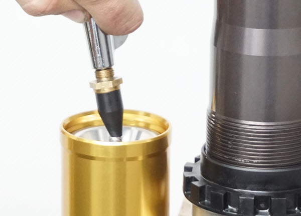
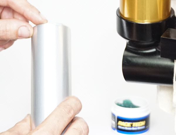
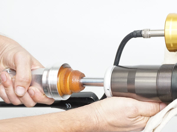
A1 - Put a small amount of Ultra Slick Seal Grease on the outer edge of the inner tube to lube the o-ring in the shock. This shows a manual bleed. If you have a Vacuum Bleeder (TSVM 01) (click here). |
|
|
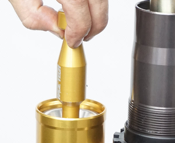
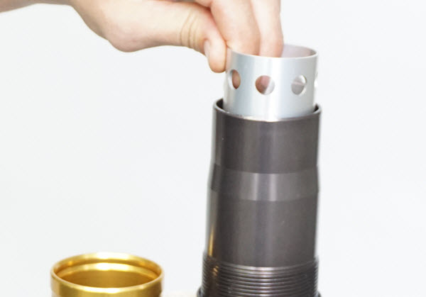
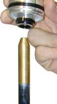
A2 - Install the inner tube into the shock body with the holes up.
|
|
|
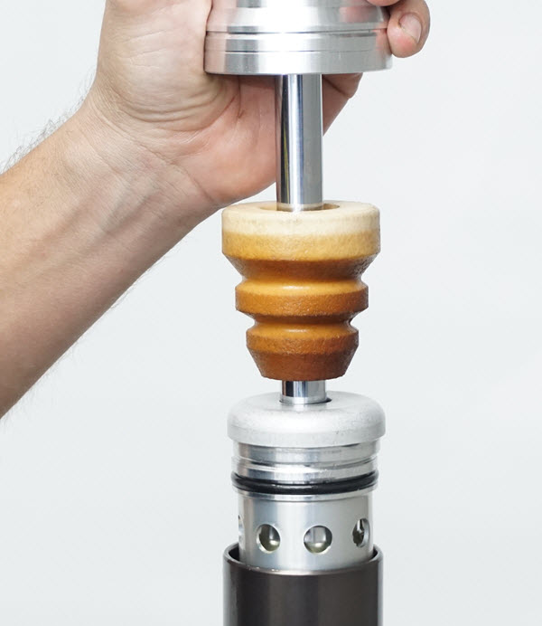
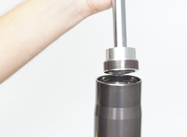
A3 - Insert the shock shaft assembly into the inner tube.
|
|
|
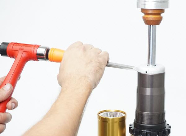
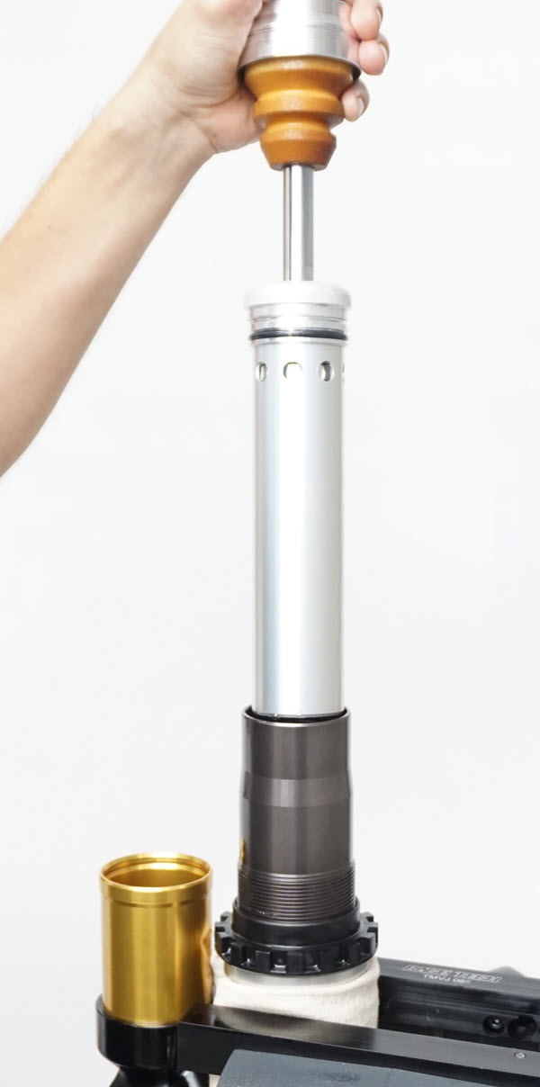
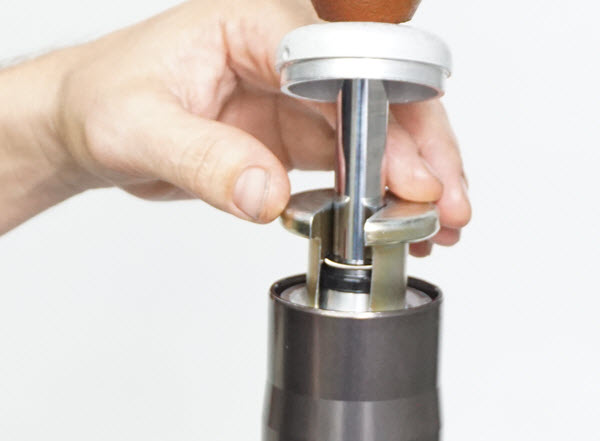
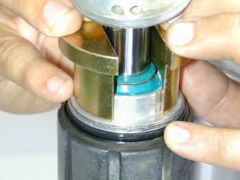
A4 - Use the Seal Head Setting tool and push the seal head down as far as you can. It will need to go further as the seal head is press fit into the inner tube.
|
|
|
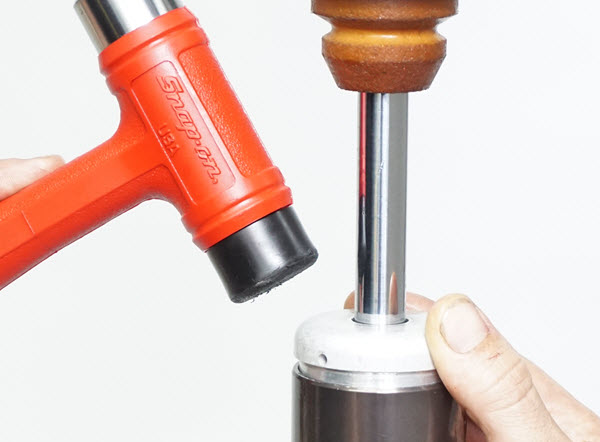
A5 - Invert the shock. Rest the Seal Head Setting Tool on the vise jaws in the "V". Use a plastic mallet and tap on the end of the shock body to seat the seal head.
Install the circlip completely into the groove.
|
|
|
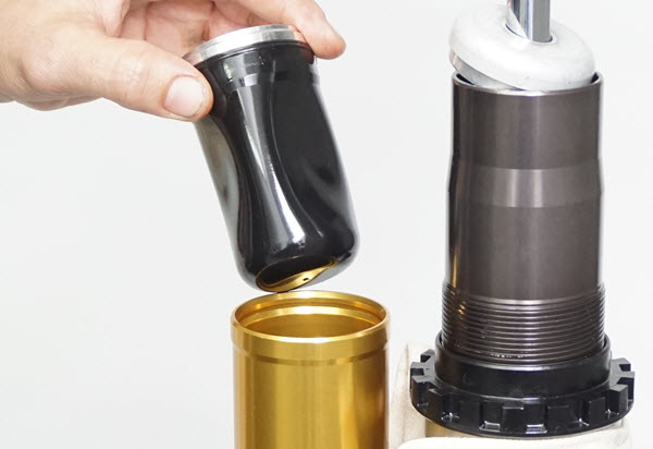
A6 - Install the Bladder Assembly and retaining circlip.
|
|
|
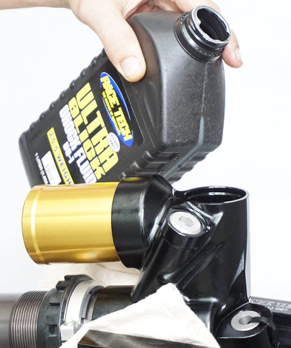
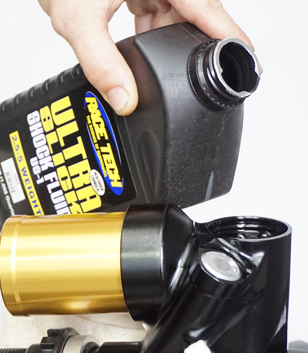
A7 - Mount the shock in the vise wrapped in a rag with the opening for the valving assembly pointing up. Start with the shock shaft compressed. Pour oil into the opening until it is nearly full.
|
|
|
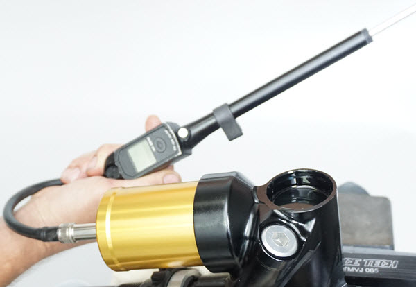
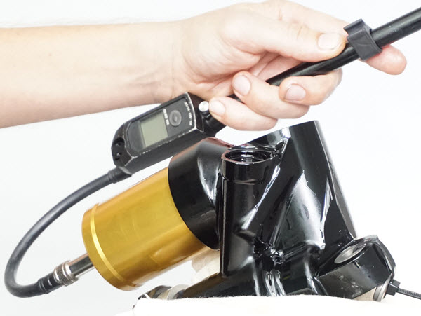
A8 - Push out air trapped in the reservoir. Attach a fork air pump (mountain bike shock pump) and pressurize the bladder to 30 psi or until bubbles stop coming out. This expands the bladder to take the full volume available inside the reservoir.
|
|
|
A9 - Stroke the shock shaft. If you want to keep oil from going all over the place this is the tricky part. Compress the shock VERY SLOWLY by twisting as you put pressure on the shock shaft.
Add oil as you extend the shock.
This method of twisting helps the shock compress slowly instead of releasing violently and making a mess.
Extend the shock using the same method of twisting and pulling slowly.
You should be able to fill the shock in one or two cycles. Watch for bubbles.
|
|
|
A10 - Top the body up with oil. Release the air in the bladder. As the bladder shrinks continue to add oil.
|
|
|
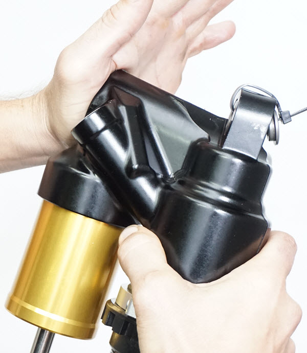
A11 - Remove the shock from the vise. Place your palm over the opening and rotate the shock around to release bubbles trapped in the corners.
|
|
|
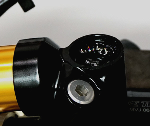
A12 - Insert the valving assembly into the oil. It will overflow. Install the circlip. Align the lettering on the face where the adjuster screws are.
|
|
|
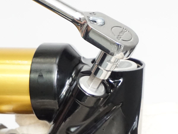
A13 - Remove the bleed plug with a 10mm allen.
|
|
|
A14 - Gently pressurize to a few psi then release the pressure. This will cycle some oil through the shock.
Put in 2 - 3 psi pressure (that is a small amount, just enough to make sure the bladder is taught.) This may not read on your gauge.
Install the Bleed Plug.
|
|
|
A15 - Align the drain holes in the body cap with the body eyelet so one is at the low point when the shock is mounted (at an angle) on the bike.
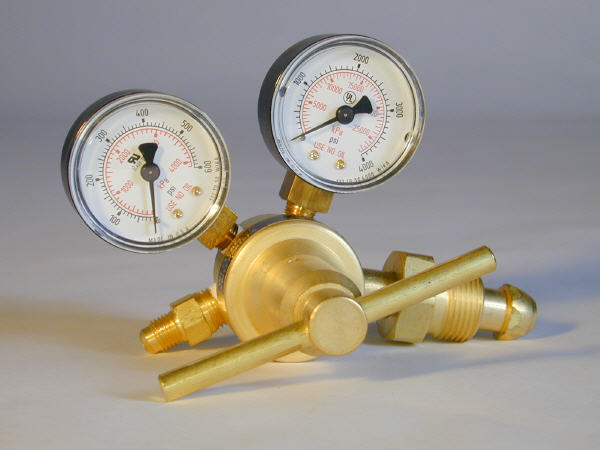
Pressurize the shock with nitrogen, install the spring with the correct preload, and set the Adjusters according to your DVS Setup Sheet.
|
|
|
A16 - Make sure bearings at the mounting eyelets are greased and in good shape with no slop.
Chicks dig stickers!
Enjoy.
|
With the switch to the new racetech website and systems we are requesting each user reset their password in our system. Simply use our forgot password feature on the login page to reset yours.
