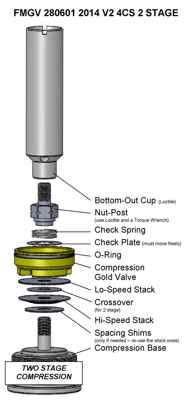
COMPRESSION GOLD VALVE INSTALLATION | |||||||
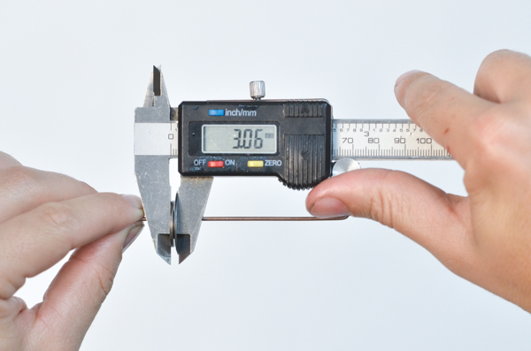
Tools Required - In-lb torque wrench that accurately measures 0 to 50 in-lbs (0.58 kgf-m) (SnapOn Digital Torque Wrench shown) - Hi-Strength Loctite (included) - Metric calipers and micrometer | |||||||
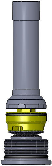
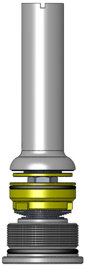
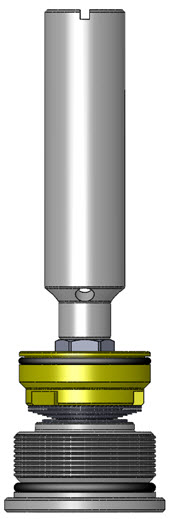
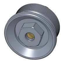
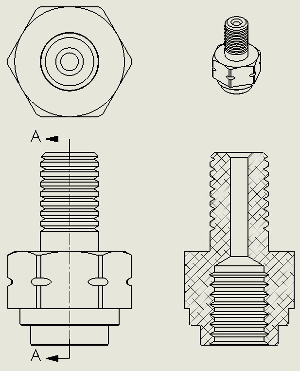
2013 | VC1- This is the Compression Base Valve. As of this printing there are 3 different types of Bottom-out Cups. 2013 and 2014 v1 have valving shims. 2014 v2 has no valving shims. 2016 there is no Bottom-out Cup. 2014 v2 | ||||||
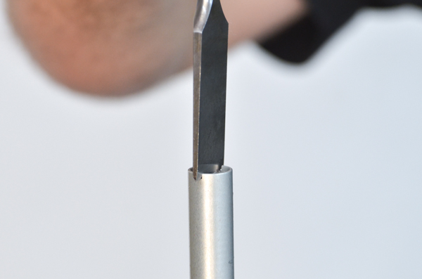
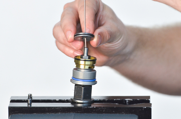
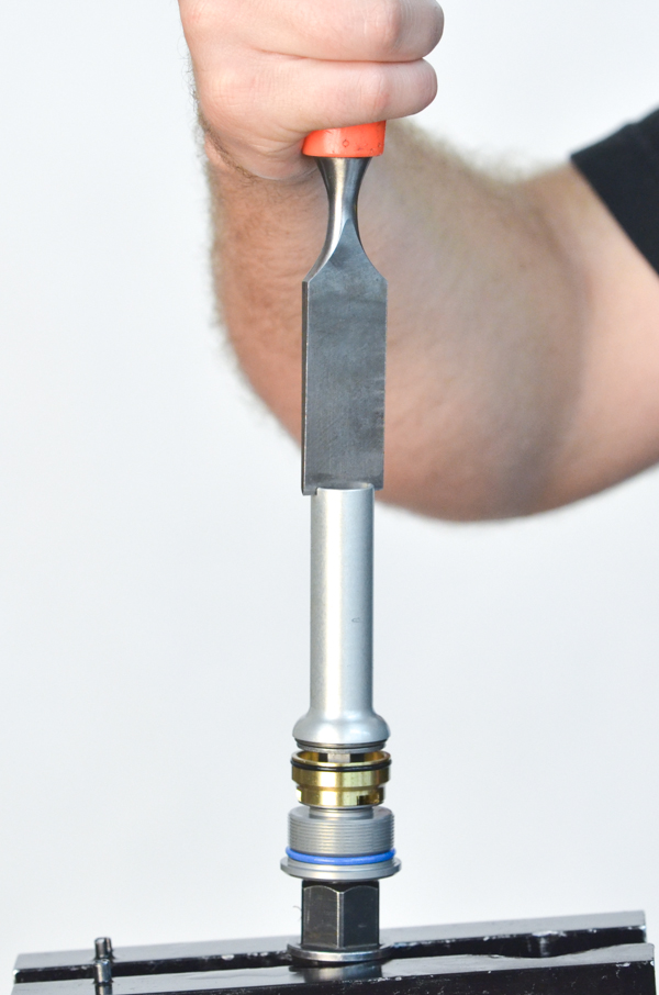
VC2- Unscrew the Bottom-out Cup, in this case, with a large screwdriver. This particular "screwdriver" is made out of a wood chisel. | |||||||
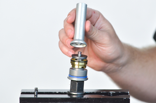
VC3- Remove the bottom-out cup. There are three different styles of bottoming cups plus none. Notice that this time the Nut-Post unscrewed from the Compression Base Valve. Sometimes the Bottom-out Cup will unscrew from the Nut-Post. Either way is fine. If it occurs like this one you can just clean it up and reinstall it during reassembly. | |||||||
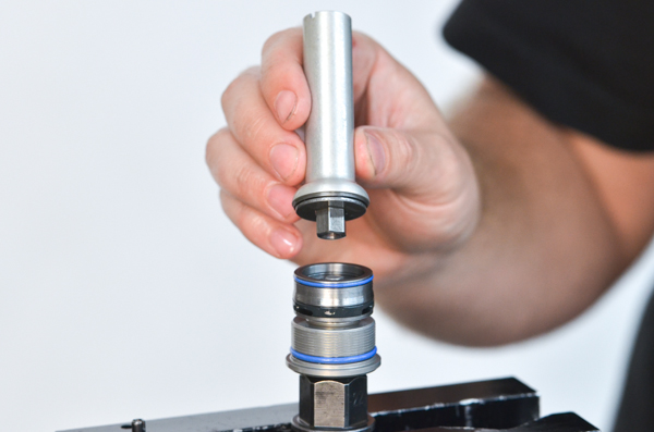
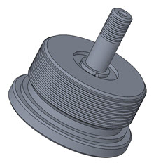
VC4- Remove the compression piston along with the valving stack. Keep track of the bottom spacing shims. You will likely need them when you build the new compression stack. | |||||||
VALVING STACK TYPES - SINGLE OR TWO STAGE VC5- You will either be building a Single Stage or a Two Stage Stack. The difference is the Crossover. The Crossover is a smaller diameter shim between the Lo-Speed and the Hi-Speed Stacks. Note: The DVS Custom Setup Sheet displays individual shims and does not label Hi-Speed, Crossover, and Lo-Speed. This is for your information only. Also you will not use all the shims provided in the Gold Valve Kit.
| |||||||
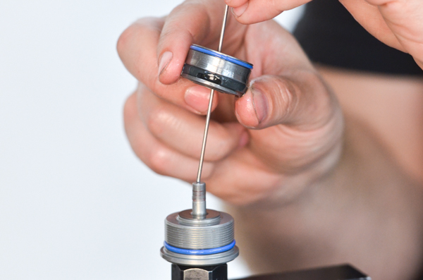
VC6- Two Stage Example (Single Stage is exactly the same except there is no Crossover) Put the valving on the shaft in the reverse of the order listed, starting with the last (smallest) shim of the Hi-Speed Stack. For Two Stage the total valving stack is made up of a: Lo-Speed Stack Crossover and a Hi-Speed Stack (this is only an example - not your setting) The Total Valving Stack starting from the Gold Valve piston face: (4) .15x24 - Lo- Speed Stack (1) .10x16 - Crossover (notice the smaller diameter) (1) .10x24 - Hi- Speed Stack (1) .10x22 (1) .10x20 (1) .10x18 (1) .10x16 (1) .10x15 (1) .10x14 (1) .10x13 (1) .10x12 | |||||||
VC7- COMPRESSION BLEED HOLE No Compression Bleed Holes are required on 4CS forks. | |||||||
VC8- SET THE TOTAL VALVING STACK THICKNESS (This is critical!) Before installing the valving on the shaft build the Valving Stack and measure the total thickness. Make sure it is between 2.7 and 3.1mm thick. If it is not, re-use some of the original .40x18 Spacing Shims to get into this range. | |||||||
VC9- This conversion eliminates the Compression Adjuster at the top of the Left Fork Leg that doesn't do much anyway. Convert it to a Rebound Adjuster by removing both Check Needles inside the Bottom-out Pistons. To get external compression adjustment RT has LSV Adjustable Compression Bases (FACB M3010001) available. If you have them use them at this time. Note - select YES LSV (Low Speed Valve) in the DVS. | |||||||
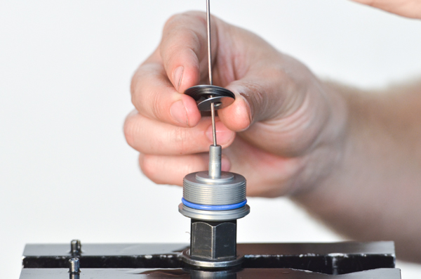
VC10- Install the compression valving stack starting with the packing shims. | |||||||
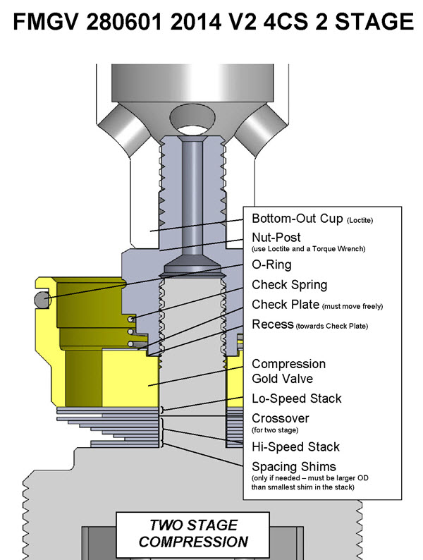
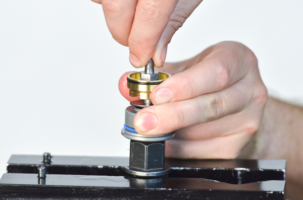
VC11- Install the Gold Valve on the shaft. Then the Check Plate and Check Spring. Put a drop of Loctite on the female thread of the Nut post. | |||||||
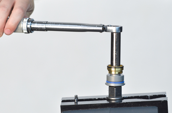
VC12- Tighten the Nut Post. CAUTION! The threads can be damaged without extreme care. The Nut-Post must be torqued with a torque wrench to 30 in-lbs (2.5 ft-lbs or 0.35 kgf-m), NO MORE! Do not take this step lightly. | |||||||
VC13- Install the original Bottom-out Valving Stack (if required). Duplicate the original setup. As of this printing there are three different Bottom-out Cup designs. Duplicate the original setup. The Bottom-out Cup Assembly screws onto the Nut-Post. Use Loctite on the female thread and torque it to 30 in-lbs. | |||||||
VC14- Install the Bottom-out Cup (if required). | |||||||
VC15- Using a large screwdriver, tighten the bottom-out cup to 30 in-lbs (2.5 ft-lbs or 0.35 kgf-m). | |||||||
| VC16- Single Stage | VC16- Two Stage | ||||||
VC17- Visually check your work. Hold the Compression Stack up to the light and look for proper assembly. If there are any problems, disassemble the stack and look for burrs to surface and/or dirt in the valving. Reassemble and check again. On two-stage stacks make sure the Crossover Gap is clearly visible. Make sure the o-ring is on the Gold Valve. | |||||||
VC18- Make sure the shims that go next to the Gold Valve completely cover the ports on both sides of the piston! If the ports are not covered there will not be enough damping. This could be caused by a number of reasons. Please call Tech Support if this occurs and you can't figure it out. | |||||||
VC19- Return to the rebuild instructions and continue with Rebound Valving and Assembly. | |||||||
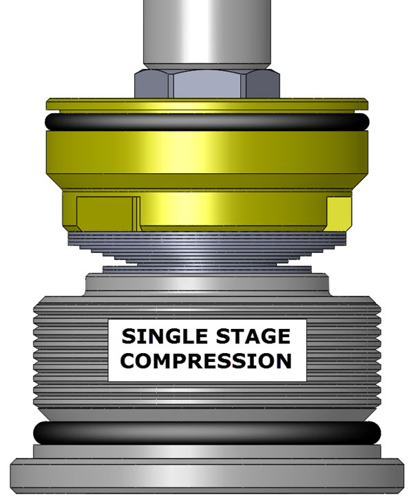

| • Single Stage - made of: Lo-Speed Stack Hi-Speed Stack There is NO Crossover | 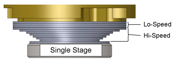 | 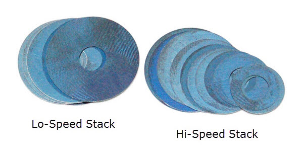 |
| • Two Stage - made of: Lo-Speed Stack Crossover Hi-Speed Stack The Crossover Gap is visible | 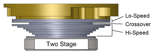 | 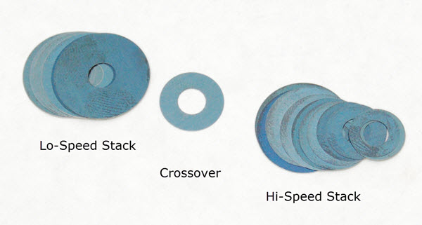 |