Skip to content
RT_E2_Logo

SUSPENSION & ENGINES

  • SEARCHES
    • Product Search
    • DVS Valving Search
    • Spring Rate Search
    • TNK Fork Tube Search
    • Instructions Search
    • Basic Setup Search
    • Engine Search
  • PRODUCTS
    • Suspension
    • Engines
    • Lubricants
    • Tools
      • Fork Tools
      • Shop Tools
      • Shock Tools
      • Dyno Mounts – CTW and Roehrig
      • Engine Tools
    • RT Merch
    • Stickers-Banners
    • Suspension Bible
    • Vintage (pre-2000)
  • SERVICES
    • Suspension
    • Engines
    • Brake Arcing
    • Race Tech Centers
  • ABOUT
    • About Race Tech
    • Contact Us
    • RT Policies
    • Rider Support
  • RESOURCES
    • Instructions
    • Service Request Forms
    • Shipping
    • Contact Us
    • Suspension Bible
    • Mental Edge Video
    • Seminars
    • Downloads
  • LOGIN
  • CART
PRODUCT SEARCH
DVS VALVING SEARCH
SPRING RATE SEARCH
ENGINE SEARCH

Fork Mid-Valve Float
How it Works and Setup

Mid-Valve Float is perhaps the most critical part of fork valving. This information is here to assist you in your understanding. THE CORRECT FLOAT AND VALVING ARE ALREADY CALCULATED IN THE DVS.

Float is affected by production tolerances. If everything is perfect, meaning you build the stack correctly and we did our homework, you can just build the mid- valve and go. However it is best to check the Float with a feeler gauge and make sure you get it right (section 3)!

- Float is the distance the Mid-Valve Stack moves before it has to bend.

The Mid-Valve creates compression damping on the Rebound Piston. The compression damping of the Mid-Valve adds to the compression damping made at the Compression Base Valve. Mid-Valve setup can be a significant portion of the total compression damping and therefore should always be setup in conjunction with the Compression Gold Valve.


For more details check out the following explaination and example. These instructions are general and not specific to your particular bike.

DVS Setup Sheet - If you haven't already, go to DVS Valving Search, insert your Access Code, and rider data and print your DVS Setup Sheet.

1. HOW THE MID-VALVE WORKS
2. BUILDING THE MID-VALVE STACK
3. CHECK THE FLOAT
4. HOW FLOAT IS CALCULATED

1A - HOW THE MID-VALVE WORKS
The Mid-Valve creates compression damping and is located on the Rebound Piston. This compression damping is added to the damping created at the Compression Valve.
Before there is movement on the compression stroke the Check Spring holds the Mid-Valve closed.

1B - HOW THE MID- VALVE WORKS
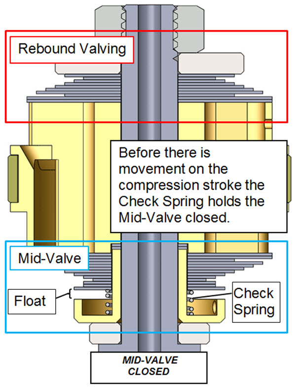
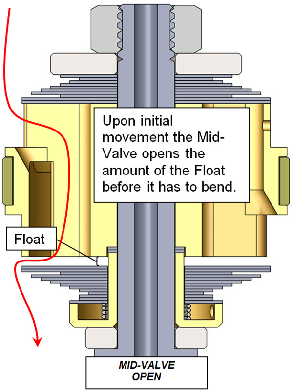
The Check Valve Spring is very soft. Once there is movement of the damper the Mid-Valve opens the amount of the Float before it has to bend.
 - Float is the distance the Mid-Valve Stack moves before it has to bend.
This Float can have the largest effect on total compression damping and can be greatly affected by production tolerances.


1C - HOW THE MID- VALVE WORKS
At higher compression velocities the Mid-Valve bends. This means the stiffness of the Mid-Valve Stack is important too. You might notice we have displayed a 2-stage Mid-Valve stack. Quite often this is a single stage stack.

2 - BUILDING THE MID-VALVE STACK
Install the Mid-Valve onto the Valving Shaft starting with the:
  Sleeve Washer
Check Spring
Mid-Valve Stack (including the Packing Shims)
     and  (if required)
  Sleeve Extender Shim(s) (if they are used, the DVS lists these at the beginning of the MV Stack)
Install the Rebound Gold Valve and the rest ot the Rebound Valving. Make sure the mid-valve is free to move up and down. Be sure to use Loctite and a torque wrench and tighten the nut to the amount on the DVS.
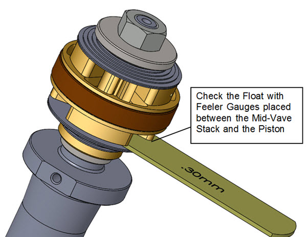
Once the complete assembly is built, check the Float with a feeler gauge (section 3).
If the assembly is built perfectly this should be correct. However, in reality, this may be off due to production tolerances on any or all of the parts in the assembly. If it is off, check your work and adjust the Packing Shims to create the correct Float.

3 - CHECK THE FLOAT
Float is the amount the stack moves before it has to bend.
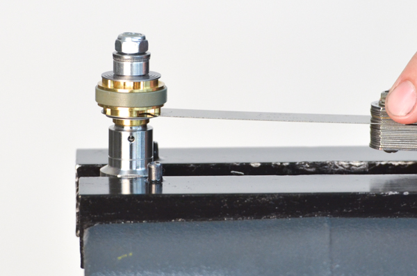
FLOAT is the most critical valving setup in the entire front fork. Once the Rebound Piston Assembly is torqued to spec use a feeler gauge to measure the "actual float" of the mid-valve. 
Insert the feeler gauge between the Gold Valve Piston face and the first shim. Make sure the feeler gauge goes all the way in to the surface of the inner sleeve.
This is the best way to check the float as there are always production tolerances that will throw the actual float off of the theoretical number.
Check your work for errors in the build.
Adjust the Sleeve Extenders or Packing Shims (the last shims closest to the check spring) to get the correct float. THIS IS CRITICAL!


4 - HOW FLOAT IS CALCULATED
(If you really must - here are the details)
FLOAT
Float is the distance the Mid-Valve Stack opens before it has to bend.
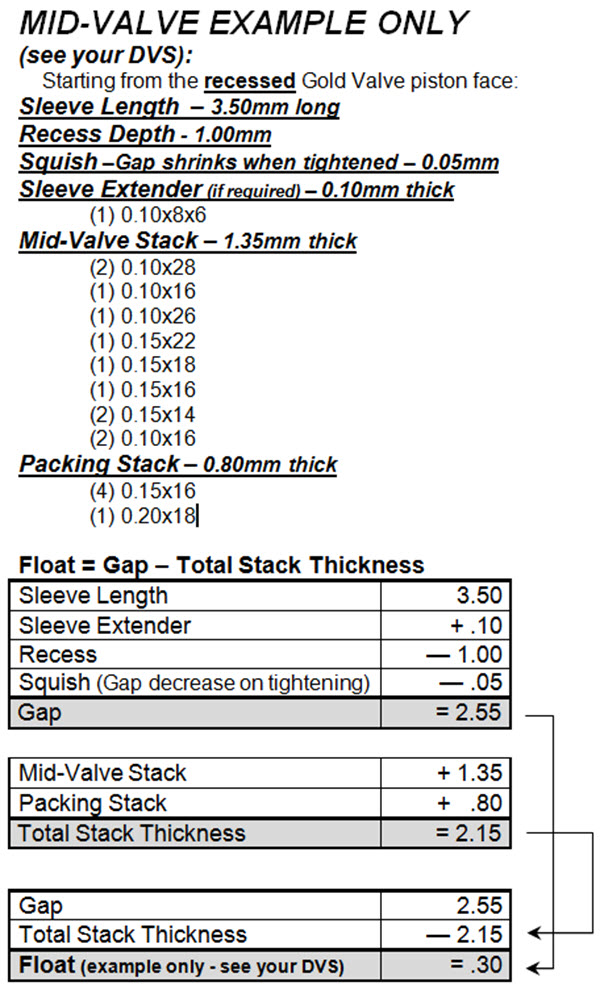
Float = Gap - Total Stack Thickness
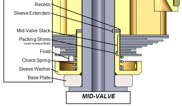
RECESS
The depth of the pocket in the piston face.
SLEEVE EXTENDER SHIMS
Sleeve Extender Shims have the ID of the shaft and the OD of the built-in sleeve of the Sleeve Washer. They effectively extend the length of the sleeve.
SLEEVE LENGTH
The Sleeve Length is the amount the sleeve sticks up above the surface of the built-in cupped washer.
GAP
Gap is the total length available for the Mid-Valve Stack...
Gap = Sleeve Length plus Sleeve Extender - Recess Depth - Squish
SQUISH
This one is a secret (don't tell anyone). Squish is the amount the Float decreases when the Nut is tightened as the components compress. It is already calculated into the theoretical float on the DVS Custom Setup Sheet. It is typically .05mm.
TOTAL STACK THICKNESS
The total height of the Mid-Valve stack including the Packing Shims. (Does not include Sleeve Extenders.)
PACKING SHIMS
Packing Shims are part of the Mid-Valve Stack. They are the first ones that go on the Sleeve Washer and are the furthest away from the Rebound Gold Valve. They are below the Clamping Shim (the smallest diameter shim in the stack), Their thickness is adjusted to fine tune the Float.


RT_E2_Logo

951.279.6655

info@racetech.com

1501 Pomona Rd. Suite 101
Corona, CA 92878

STOP! Include Service Request Form when shipping components to Race Tech.

twitter link facebook link instagram link

© 2025 Race Tech. All Rights Reserved

  • Downloads
  • Dealer Application
  • Policies
  • Cookie Policy (EU)
Race Tech
We Respect Your Privacy
To provide the best experiences, we use technologies like cookies to store and/or access device information. Consenting to these technologies will allow us to process data such as browsing behavior or unique IDs on this site. Not consenting or withdrawing consent, may adversely affect certain features and functions.
Functional Always active
The technical storage or access is strictly necessary for the legitimate purpose of enabling the use of a specific service explicitly requested by the subscriber or user, or for the sole purpose of carrying out the transmission of a communication over an electronic communications network.
Preferences
The technical storage or access is necessary for the legitimate purpose of storing preferences that are not requested by the subscriber or user.
Statistics
The technical storage or access that is used exclusively for statistical purposes. The technical storage or access that is used exclusively for anonymous statistical purposes. Without a subpoena, voluntary compliance on the part of your Internet Service Provider, or additional records from a third party, information stored or retrieved for this purpose alone cannot usually be used to identify you.
Marketing
The technical storage or access is required to create user profiles to send advertising, or to track the user on a website or across several websites for similar marketing purposes.
Manage options Manage services Manage {vendor_count} vendors Read more about these purposes
View preferences
{title} {title} {title}
Scroll To Top